Image forming apparatus using peak AC potentials to move toner toward an image bearing member and a developer carrying member, respectively

a technology of image forming apparatus and ac potential, which is applied in the direction of electrographic process apparatus, instruments, optics, etc., can solve the problems of easy disturbance of formed electrostatic image, low surface resistance, and disturbance of electrostatic image, and achieve excellent development properties

Inactive Publication Date: 2010-05-11
CANON KK
View PDF11 Cites 5 Cited by
  • Summary
  • Abstract
  • Description
  • Claims
  • Application Information

AI Technical Summary

Benefits of technology

[0045]An object of the present invention is to provide an image forming apparatus which uses a dual-component developer including a toner and a carrier and is capable of obtaining an excellent development property while preventing an injection of electric charges into the electrostatic image through the carrier.
[0046]Another object of the present invention is to provide an image forming apparatus having a developing device that employs a developing method in which the development property is enhanced exponentially by the use of a high permittivity carrier in development.
[0047]Still another object of the present invention is to provide an image forming apparatus having a developing device that employs a developing method in which the development property is enhanced exponentially irrespective of the use of a high charge amount toner.
[0048]Yet still another object of the present invention is to provide an image forming apparatus capable of forming high definition images steadily for a long period of time irrespective of the use of a large capacitance photosensitive member.

Problems solved by technology

However, increasing the developing bias to a level higher than necessary may cause an injection of electric charges from the developer carrying member into the electrostatic image through the carrier, which disturbs the electrostatic image.
A drawback of a-Si photosensitive members is that their surface resistance is lower than that of OPC photosensitive members, which makes the influence of the above-mentioned charge injection from the developer carrying member through the carrier in a-Si photosensitive members much greater than the one in OPC photosensitive members.
Therefore, when an a-Si photosensitive member is employed, a formed electrostatic image can easily be disturbed by the charge injection and the traveling of electric charges has to be restricted even more than when an OPC photosensitive member is employed by lowering the peak-to-peak voltage, Vpp, of the developing bias, which is alternating bias.
Lowering Vpp of the developing bias reduces electric charges injected from the developer carrying member to the photosensitive member through the carrier, but weakens the electric field applied to the developer.
However, setting the electric resistance of the carrier high is known to tend to lower the development property, in other words, the ability to detach (discharge) the toner from the carrier.
In charging the toner, the electric resistance of the carrier set high makes it difficult for electric charges accumulated in the carrier to travel.
The electric charges in the carrier and electric charges in the toner thus attract each other, thereby generating a large attractive force and hindering the toner from detaching from the carrier.
Also when the alternating bias is switched to apply the pull-back direction bias, the toner is subjected to a higher electric field intensity and more toner particles are detached from the photosensitive member with the high permittivity carrier A than with the low permittivity carrier B, which is inconvenient in that the influence of the permittivity on the development property is weakened.
The development property degrades as the capacitance (per-unit area capacitance) of the photosensitive member increases and, when the degradation progresses beyond allowable limits, various image defects occur.
However, in the quick printing market or the like where a wide range of tone reproduction is required, the γ characteristic (characteristic of the image density in relation to the image exposure amount) at Vcont=147 V may be too sharp to attain a high tone reproduction property, with the result that a halftone image such as a photographic image is difficult to be reproduced.
Also in those cases, a reduction in film thickness of the photosensitive member causes an increase in capacitance of the photosensitive member, which may cause the same problem as the one described above regarding a-Si photosensitive members.
In practice, however, increasing the toner charge amount Q / M [μC / g] increases the electrostatic force of the carrier and the toner significantly, and may seriously degrade the development property.

Method used


Image

  • Image forming apparatus using peak AC potentials to move toner toward an image bearing member and a developer carrying member, respectively
  • Image forming apparatus using peak AC potentials to move toner toward an image bearing member and a developer carrying member, respectively
  • Image forming apparatus using peak AC potentials to move toner toward an image bearing member and a developer carrying member, respectively

Examples


first embodiment

[0068]

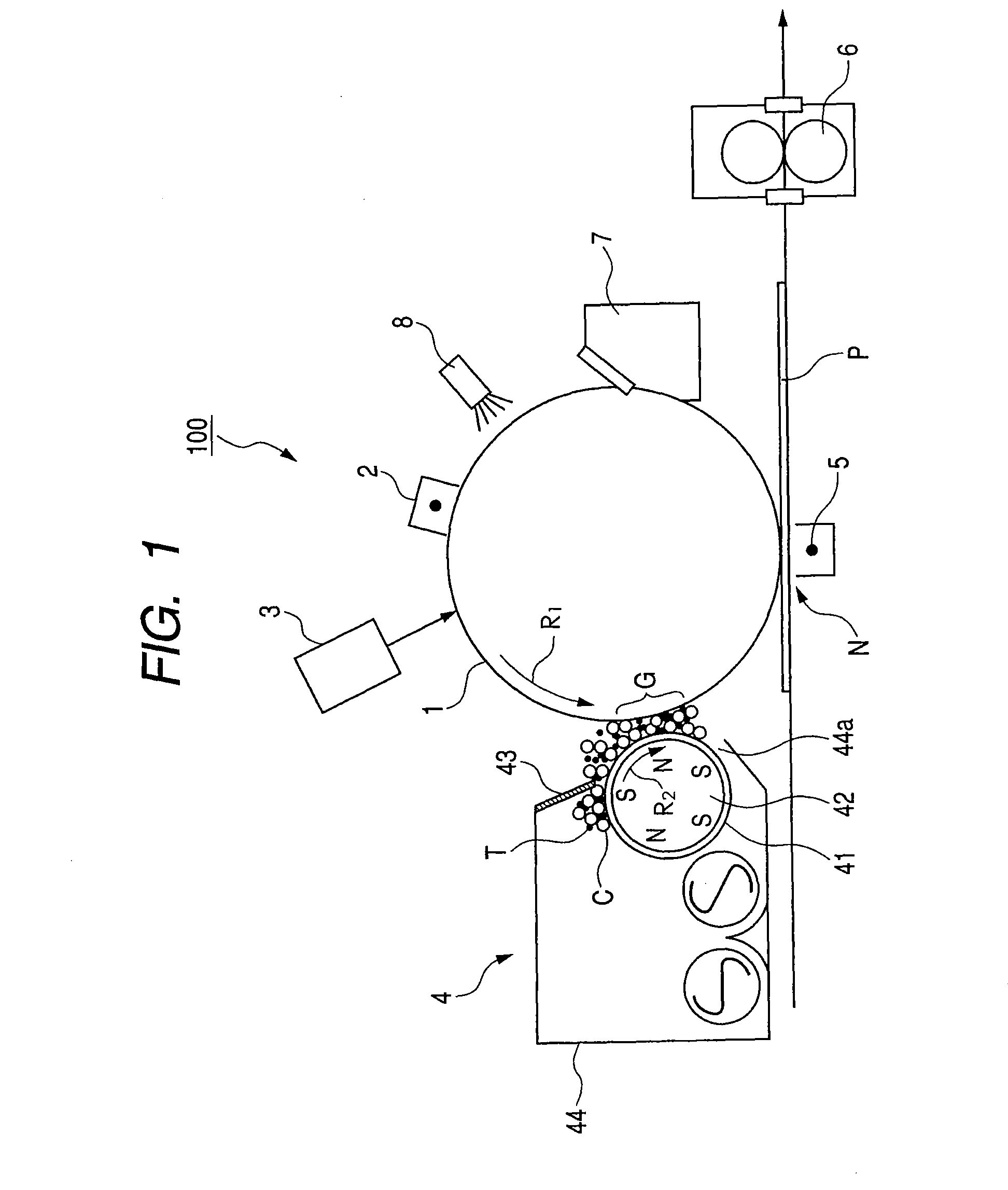
[0069]FIG. 1 illustrates the schematic, sectional structure of important parts of an image forming apparatus 100 according to an embodiment of the present invention.

[0070]The image forming apparatus 100 has a cylindrical electrophotographic photosensitive member (hereinafter simply referred to as “photosensitive member”) 1, which is a so-called photosensitive drum and serves as an image bearing member. Arranged around the photosensitive member 1 are a charger 2, which is a charging measure, an exposure device 3, which is an exposing measure, a developing device 4, which is a developing measure, a transfer charger 5, which is a transferring measure, a cleaner 7, which is a cleaning measure, a pre-exposure device 8, which is a pre-exposing measure, and the like. A fixing device 6 which is a fixing measure is placed along a direction in which a transfer material P is transported at a point downstream of a transfer portion N where the photosensitive member 1 and the transfer charg...

specific example

[0143]FIG. 13 illustrates a specific example of the electric potential of the electrostatic image on the photosensitive member 1 and the developing bias applied to the developing sleeve 41 in an actual developing operation. In FIG. 13, the axis of abscissa illustrates the time and the axis of ordinate illustrates the electric potential.

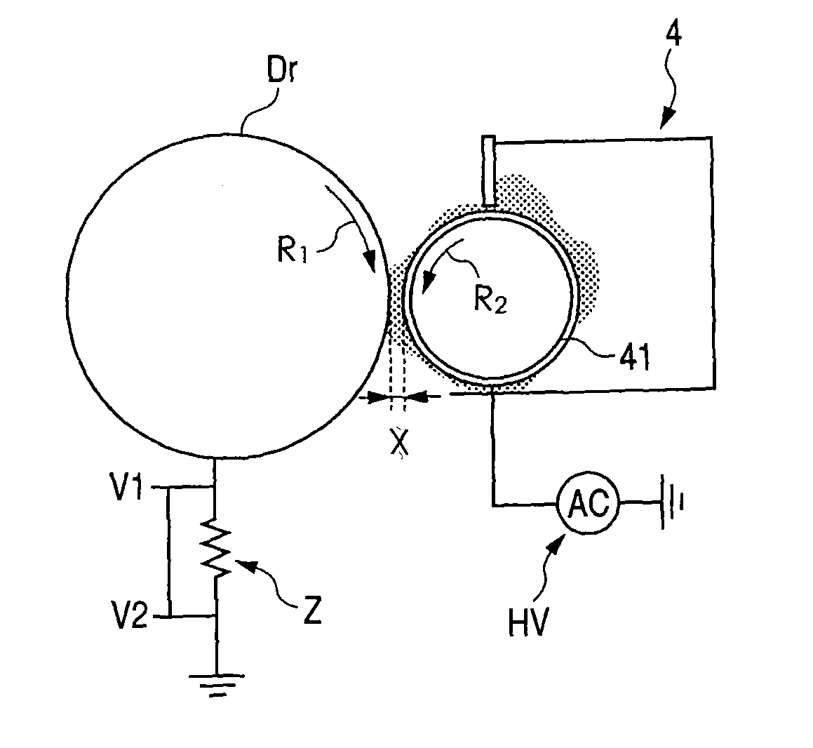
[0144]This specific example employs, as the developing bias, rectangular wave developing bias (alternating bias) in which Vpp=1.8 kV, the DC voltage component Vdc=−350 V, and a frequency f=12 KHz (one cycle: 83.3 μsec). This developing bias is applied between the electrostatic image on the photosensitive member 1 and the developing sleeve 41.

[0145]The electrostatic image in this specific example is formed by the image exposure method. The toner in this specific example is charged with negative electric charges by friction with the carrier. The developing method employed in this specific example is the reverse developing method.

[0146]VD in FIG. 13 repr...


PUM


Abstract

An image forming apparatus includes a photosensitive drum to which an electrostatic image is formed and a developing sleeve carrying a developer including toner carrier. An alternating voltage is applied to the sleeve to form an alternating electric field between the sleeve and the drum to develop the electrostatic image with the developer. A relation |K1|<|K2| is satisfied, where K1: a slope at an electric field intensity Ed=|(Vp2−VL) / D|, K2: a slope at an electric field intensity Eb=|(Vp1−VL) / D|, VL: a potential [V] of the electrostatic image at which a maximum density is obtained, Vp1: a peak potential [V] that provides a potential difference to move the toner toward the drum, Vp2: a peak potential [V] that provides a potential difference to move the toner toward the sleeve, and D: a closest distance [m] between the drum and the sleeve.

Description

BACKGROUND OF THE INVENTION[0001]1. Field of the Invention[0002]The present invention relates to an image forming apparatus such as a copier or a printer that obtains an image by using a toner to visualize an electrostatic image formed on an image bearing member. More specifically, the present invention relates to an image forming apparatus that employs as its developer a dual-component developer which has a toner and a carrier.[0003]2. Description of the Related Art[0004]In conventional copiers, printers, and other image forming apparatuses that use an electrophotographic process, a surface of an electrophotographic photosensitive member (hereinafter simply referred to as “photosensitive member”) serving as an image bearing member is charged uniformly, and the surface is then exposed to light in a pattern determined by image information. An electrostatic image (latent image) is thus formed on the surface of the photosensitive member. The electrostatic image formed on the photosensi...

Claims


Application Information

Patent Timeline
Patent Type & Authority Patents(United States)
IPC IPC(8): G03G15/00G03G15/09
CPCG03G15/0907G03G2215/0607
Inventor MIYAZAWA, TOMOAKIYAMAMOTO, TAKESHIHARAGUCHI, MANAMIKUBO, KENTAHORIE, JUUN
Owner CANON KK
Why Eureka
Try Eureka