Multicontrolled brewer for optimum flavor extraction

a multi-controlled, optimum technology, applied in beverage vessels, household appliances, kitchen equipment, etc., can solve the problems of not achieving maximum extraction and optimum flavor

Active Publication Date: 2010-05-18
FOOD EQUIP TECH
View PDF8 Cites 73 Cited by
  • Summary
  • Abstract
  • Description
  • Claims
  • Application Information

AI Technical Summary

Benefits of technology

[0007]This objective is achieved in part by providing a hot beverage brewer having a source of hot water, a brew basket assembly for holding beverage ingredient, a water dispense system for selectively passing hot water into the brew basket assembly under control of an electronic controller with a brew basket control system composed of a pressure source, means for selectively applying positive air pressure from the pressure source to the brew basket, and means for controlling the application of pressure to the brew basket by the selectively applying means to control the rate of seepage of hot water through a layer of beverage ingredient within the brew basket.
[0008]Preferably, the controlling means includes means for sensing pressure, and the pressure controlling means includes means responsive to the pressure sensing means for controlling the application of pressure by the selectively applying means to the brew basket. The controlling means preferably includes means for timing the brew cycle and selectively applying pressure to the brew basket assembly at preselected times during the brewing cycle to speed the rate at which the water percolates though the beverage ingredient during preselected time periods during the brew cycle in order to maximize uniform extraction and optimum flavor. Also, in the preferred embodiment the selectively applying means includes a special dispense head assembly with a manifold with an inlet and an outlet that communicates directly with an open top brew basket assembly, and a solenoid controlled pressure valve with at least one outlet in pressure communication with the brew basket assembly. The pressure source includes an electrically powered pneumatic pump, and the controlling means includes means for controlling the application of power to the pneumatic pump. The brew basket assembly has a bottom with a beverage drain hole, or opening, and in the preferred embodiment a closure gate carried by the bottom and is mounted to the bottom by mounting members for sliding movement between a closed position and an open position.
[0009]The objective is also obtained by providing a hot beverage brewer having a source of hot water, a brew basket assembly for holding beverage ingredient, a water dispense system for selectively passing hot water into the brew basket assembly with a beverage drain hole under control of an electronic controller with a brew basket flow rate control system having means for selectively closing the beverage drain hole to accumulate beverage within the brew basket assembly during preselected time periods of a brew cycle to reduce the rate of flow of beverage from the drain hole, and means for selectively applying positive air pressure to the brew basket assembly during preselected time periods of the brew cycle to increase the rate of beverage flow from the brew basket assembly drain hole.
[0013]Acquisition of the objective is also accomplished by providing a hot beverage brewer having a source of hot water, a movably mounted brew basket assembly with a brew basket for holding beverage ingredient and a drain hole to dispense beverage, a water dispense system including a brew water dispense valve for selectively passing hot water into the brew basket assembly and though the ingredient, the improvement being a brew basket control system having means for electronically measuring a light characteristic of the beverage as it flows downwardly out of the drain hole and falls freely through air to detect an indication of an instantaneous level of extraction of ingredient into the beverage, said light measuring means being located adjacent the drain hole and above the beverage container and spaced from the brew basket and the beverage container to enable removal of the brew basket without first disconnecting the light measuring means from the brew basket, and a controller responsive to the indication of the instantaneous level of extraction to control at least one of (a) a bypass valve spaced from the brew water dispense valve for passing hot water into the brew basket at a location spaced from and bypassing the ingredient, (b) means to pressurize the brew basket to hasten draining of the beverage from the drain hole, (c) a drain hole closure means and (d) an instantaneous electric hot water heater for heating hot water spaced from the hot water tank before the hot water is dispensed into the brew basket.

Problems solved by technology

While such known brewers function successfully, they sometimes fail to obtain maximum extraction and optimum flavor due to an inability to fully control brew parameters depending upon changing conditions such as room temperature, inherent percolation rates at atmospheric pressure, seepage of water out the sides of the layer of ingredient and not through the entire layer, or due to a failure to provide a uniform distribution of hot water onto the top surface of the ingredient.

Method used


Image

  • Multicontrolled brewer for optimum flavor extraction
  • Multicontrolled brewer for optimum flavor extraction
  • Multicontrolled brewer for optimum flavor extraction

Examples


Embodiment Construction

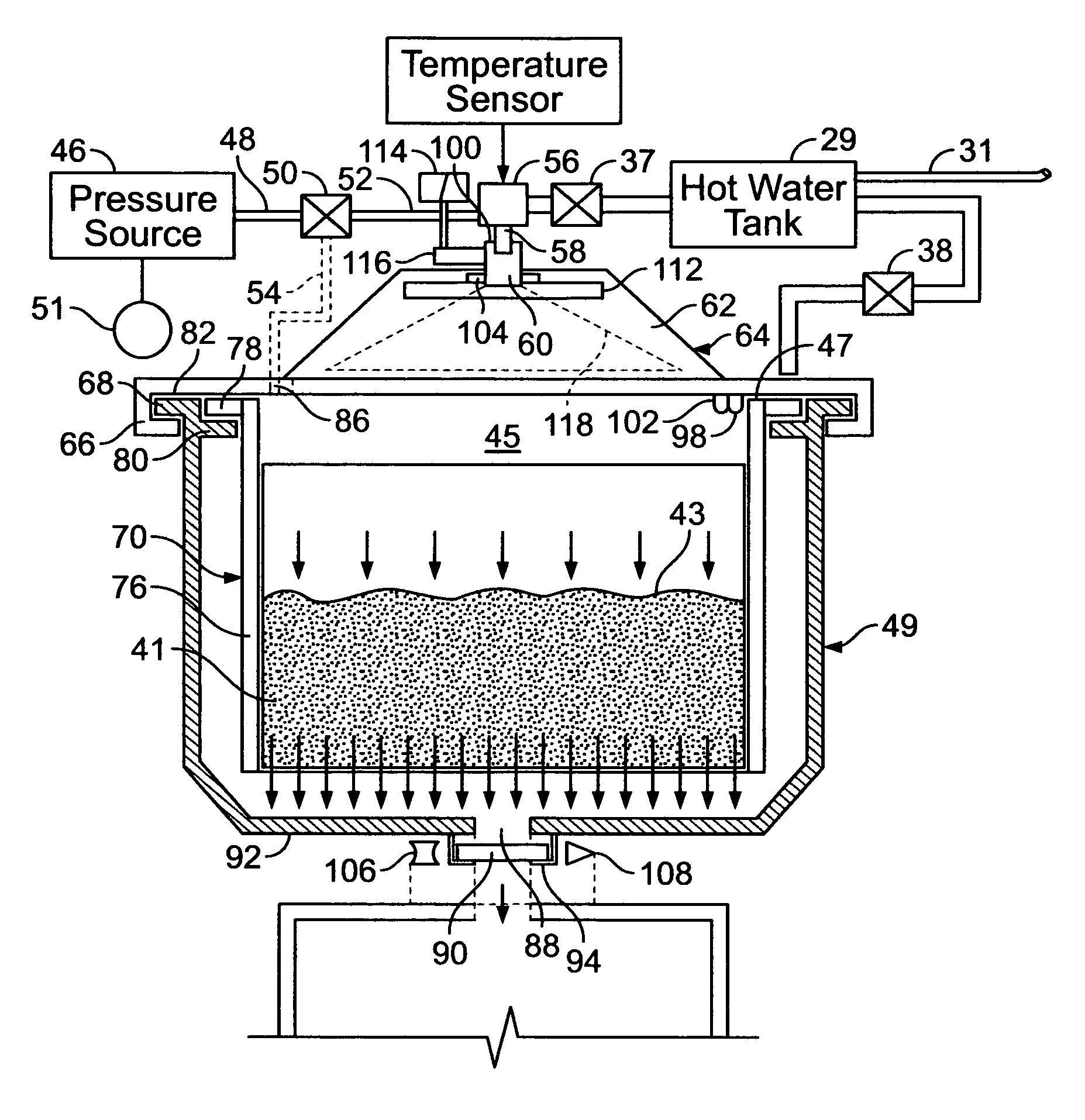
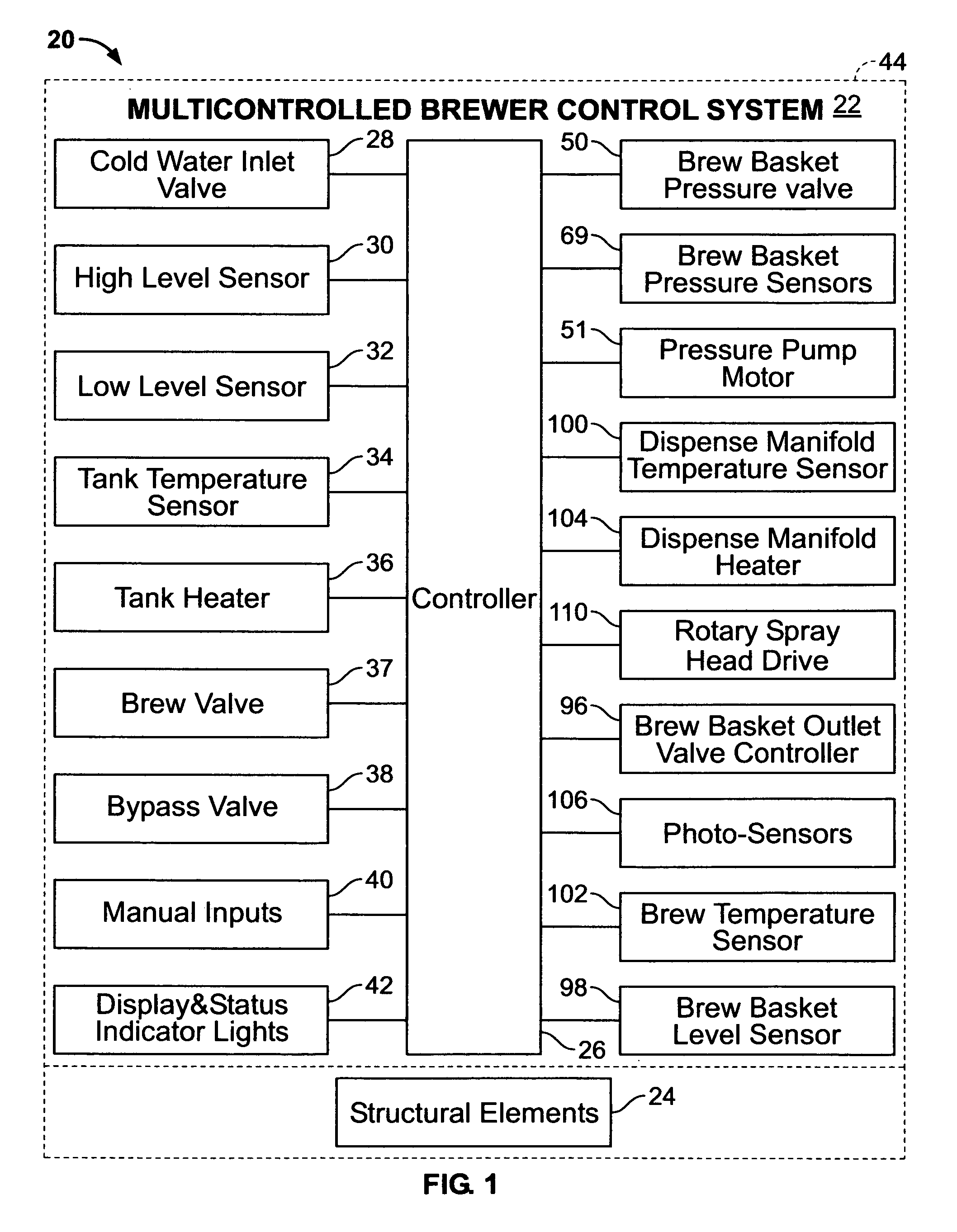
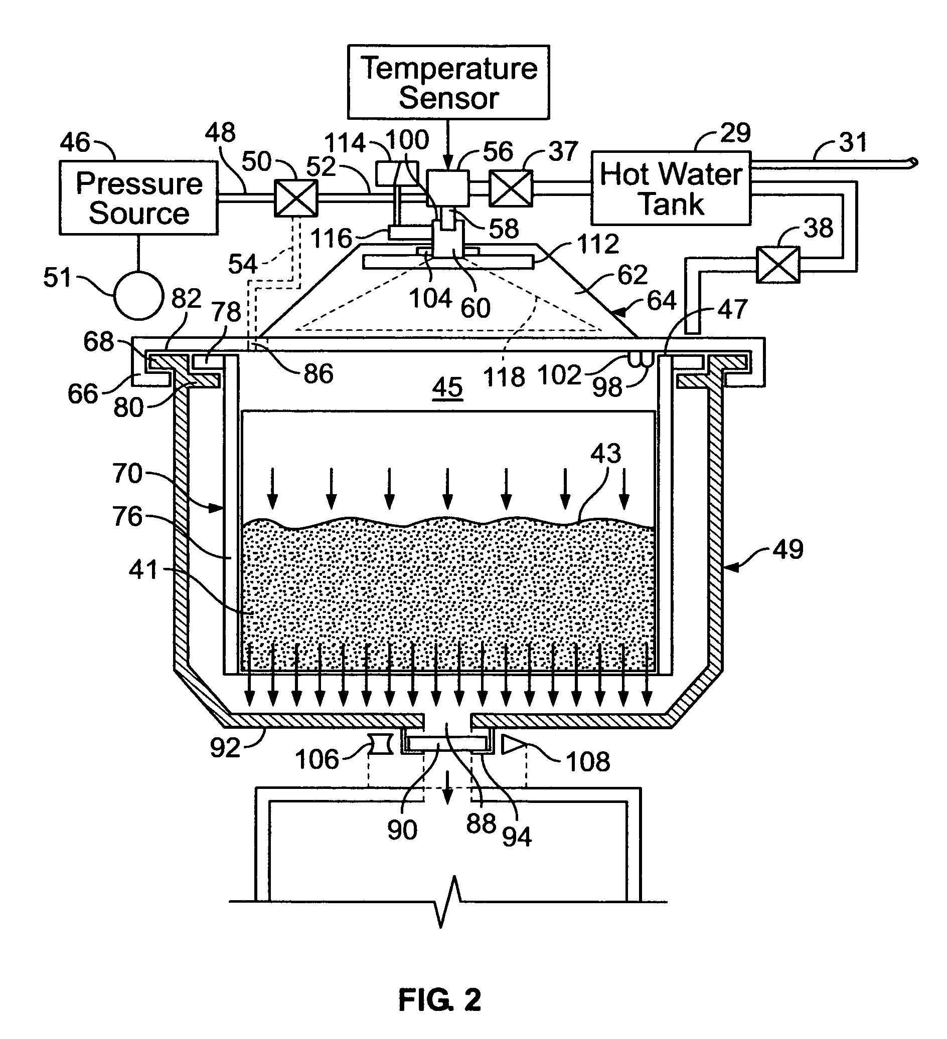
[0033]Referring now to FIG. 1, an embodiment of the multicontrolled brewer 20 of the present invention includes a multicontrolled brewer control system 22 and other structural elements, or mechanical or electromechanical, elements 24. Some of the elements of the structural elements 24 are shown in and are described with reference to FIG. 2.

[0034]Some of the elements of the control system 22 are known and, in keeping with the invention, some of the elements are novel. The known elements of the control system 22 include a controller 26 which includes a microcomputer (not shown) with all needed memory to store operating software and sensor data and programmable parameters, etc. (not shown) and all interface circuitry (not shown) needed to interface with the other control elements described below. The computer interfaces with conventional elements, but it novel to the extent that it has been programmed to interface with and sometimes control the novel elements of the control system 22 d...


PUM


Abstract

A multicontrolled, fresh beverage brewer (20) with a dispense manifold heater (104) for selectively instantaneously heating pre-heated hot water from a hot water tank (29) immediately before the preheated hot water is dispensed into the brew basket (49) in sensed temperature of the beverage within the brew basket the preheated water immediately prior to being added to the brew basket, a photosensor (106) for sensing a level of light conductance of the beverage for controlling at least one of a brew dispense valve (37), a bypass valve (38) and a brew basket drain hole closure (94) in response to photosensor sensing a level of light conductance level of the beverage, and brew basket pressurization system (50, 69, 51) for selectively pressurizing the brew basket (49) to selectively accelerate the flow rate of hot water though an ingredient within the brew basket. A rotary spray head drive (110) rotates a rotating spray assembly to provide an even distribution of hot water over the surface of the ingredient, and a spray distribution plate employs open channels of differing length (156) to channel the water to different desired location are open for easy cleaning and elimination of clogging from lime residue. A brew basket filter holder (72) insert for insertion into the filter holder has a cylindrical, water impervious wall to prevent side passage of the hot water through the layer of beverage ingredient.

Description

CROSS-REFERENCE TO RELATED APPLICATION[0001]This application claims the benefit under 35 USC 119(e) of U.S. provisional patent application of the present inventor, Ser. No. 60 / 474,088 filed May 28, 2003, which is hereby incorporated by reference.SUMMARY OF THE INVENTION[0002]1. Field of the Invention[0003]This invention relates generally to hot beverage makers and more particularly to hot beverage brewers that brew fresh beverage by passing hot water through a beverage ingredient contained within a brew basket with a beverage drain hole.[0004]2. Discussion of the Prior Art[0005]Beverage brewers of the type having a hot water dispense system for passing hot water through a beverage ingredient, such as ground coffee or tea, or tea leaves, or the like, while held within a paper filter which in turn is held within a brew basket are well know and will be described in greater detail below with reference to FIG. 1. While such known brewers function successfully, they sometimes fail to obta...

Claims


Application Information

Patent Timeline
Patent Type & Authority Patents(United States)
IPC IPC(8): A47J31/40
CPCA47J31/36A47J31/56A47J31/52A47J31/4478A47J31/525A47J31/5251A47J31/5253
Inventor LASSOTA, ZBIGNIEW G.
Owner FOOD EQUIP TECH
Why Eureka
Try Eureka