Contactless power and data transmission apparatus

a technology of contactless power and data transmission, which is applied in the direction of electric generator control, machines/engines, instruments, etc., can solve the problems of brush and slip ring mechanism, increase in weight, volume and complexity of the system,

Active Publication Date: 2010-05-18
SCHLEIFRING MEDICAL SYST USA +1
View PDF22 Cites 63 Cited by
  • Summary
  • Abstract
  • Description
  • Claims
  • Application Information

AI Technical Summary

Problems solved by technology

The high-voltage tank and inverter on the rotating gantry portion increases the weight, volume and complexity of the system.
Furthermore, the brush and slip ring mechanisms (that are typically used to carry appreciable current) are subject to reduced reliability, maintenance problems, and electrical noise generation, which interfere with sensitive electronics.
However, the voltage and current in rotating transformers used to transfer power in CT imaging systems are quite considerable.
For example, a 150 KW imaging system may have a rotary transformer that operates at approximately 300 volts and 500 amperes and that generates a considerable amount of electrical noise.
These configurations are relatively costly and complicated.

Method used


Image

  • Contactless power and data transmission apparatus
  • Contactless power and data transmission apparatus
  • Contactless power and data transmission apparatus

Examples


Embodiment Construction

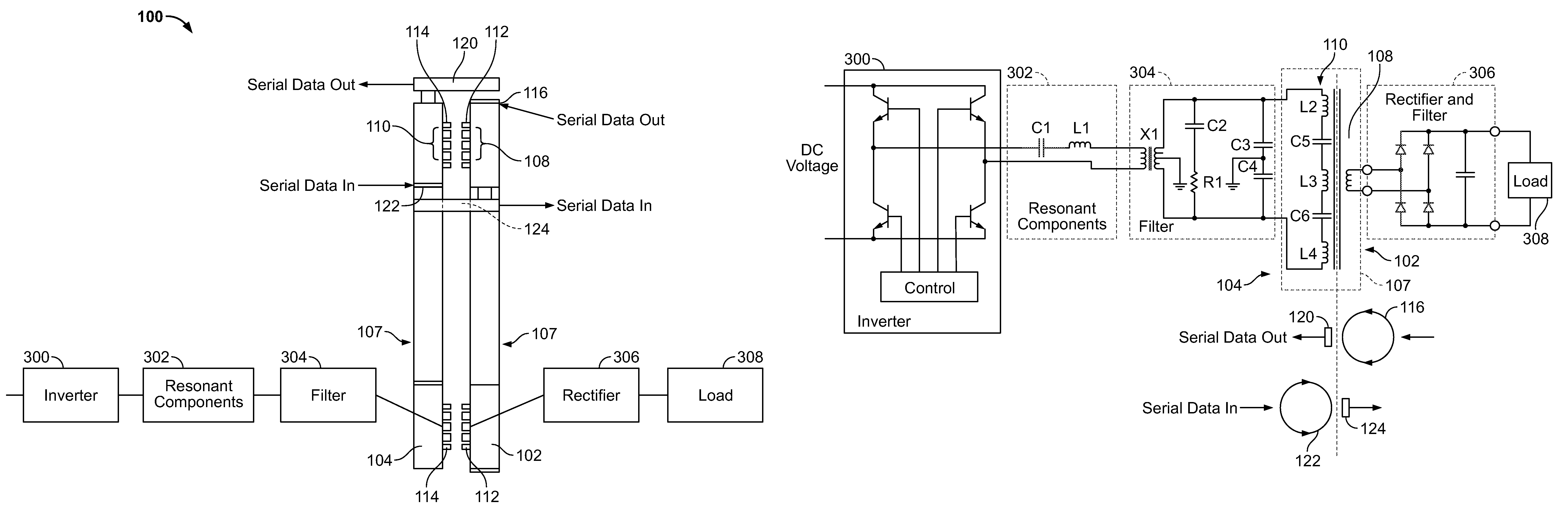
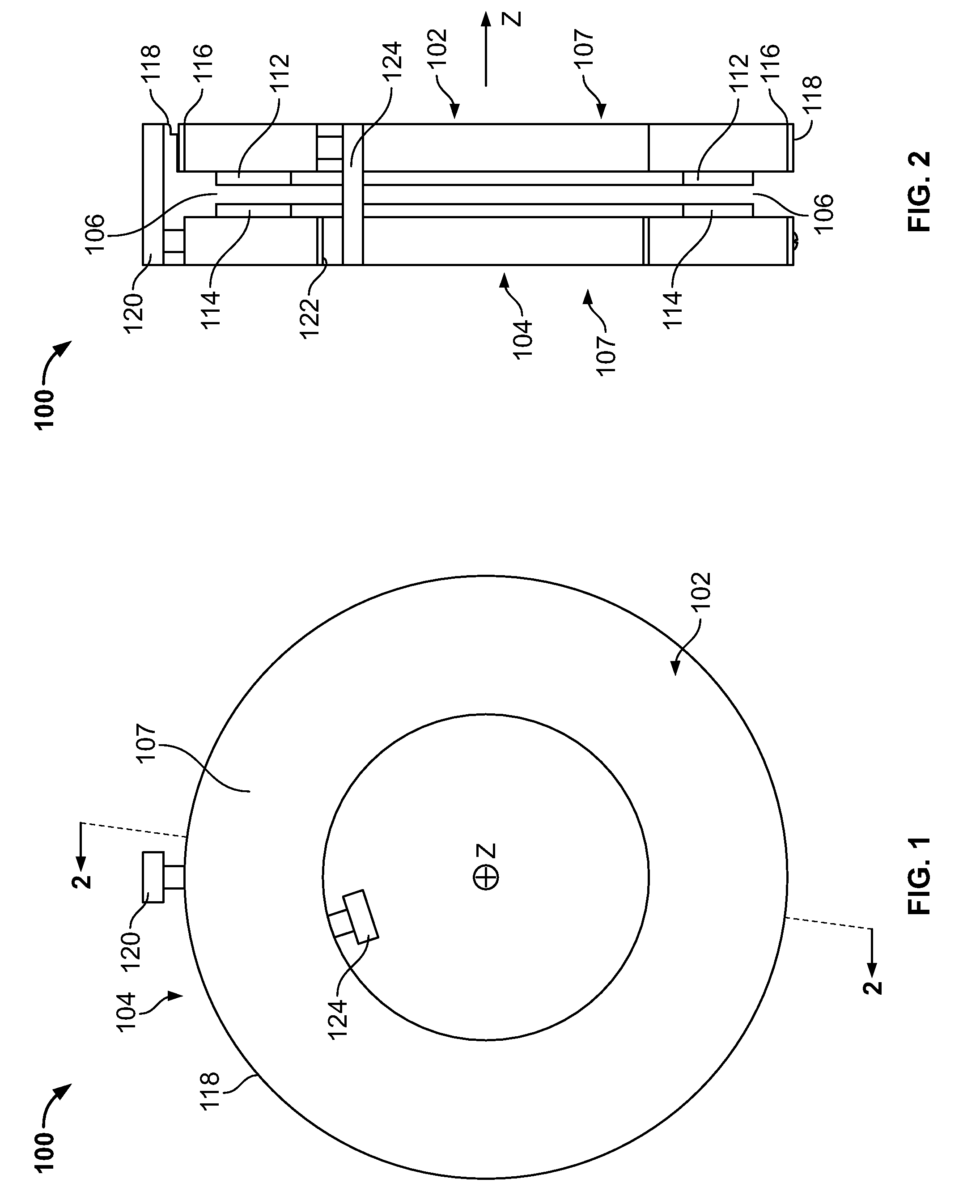
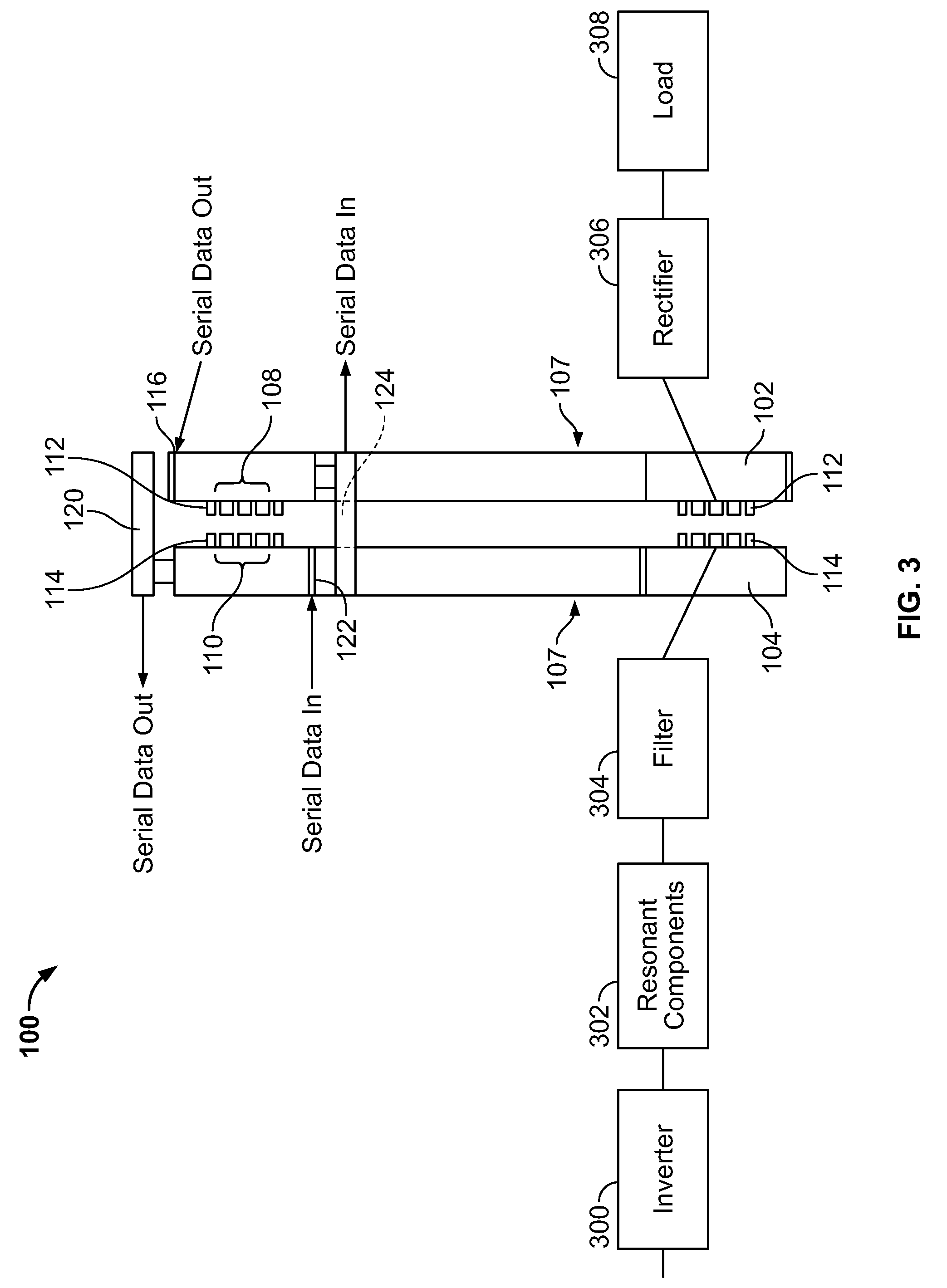
[0022]The foregoing summary, as well as the following detailed description of certain embodiments of the present invention, will be better understood when read in conjunction with the appended drawings. To the extent that the figures illustrate diagrams of the functional blocks of various embodiments, the functional blocks are not necessarily indicative of the division between hardware circuitry. Thus, for example, one or more of the functional blocks (e.g., processors or memories) may be implemented in a single piece of hardware (e.g., a general purpose signal processor or a block of random access memory, hard disk, or the like). Similarly, the programs may be stand alone programs, may be incorporated as subroutines in an operating system, may be functions in an installed software package, and the like. It should be understood that the various embodiments are not limited to the arrangements and instrumentality shown in the drawings.

[0023]As used herein, an element or step recited i...


PUM

PropertyMeasurementUnit
voltagesaaaaaaaaaa
voltagesaaaaaaaaaa
angleaaaaaaaaaa

Abstract

Methods and apparatus for an imaging system are provided. The imaging system includes a gantry having a stationary member coupled to a rotating member. The rotating member has an opened area proximate an axis about which the rotating member rotates. An x-ray source provided on the rotating member. An x-ray detector may be disposed on the rotating member and configured to receive x-rays from the x-ray source. A rotary transformer having circumferentially disposed primary and secondary windings may form part of a contactless power transfer system that rotates the rotatable portion of the gantry at very high speeds, the primary winding being disposed on the stationary member and the secondary winding being disposed on the rotating member.

Description

BACKGROUND OF THE INVENTION[0001]This invention generally relates to the transmission of data and power across a rotating interface, and more particularly, to an apparatus that can transmit both power and data across the rotating interface without requiring brushes or other contacts.[0002]High-voltage power transformers are used in a variety of applications, such as in baggage scanner systems, computed tomography (CT) systems, wind turbines, and other electronic systems. CT systems are often used to obtain non-invasive sectional images of test objects, particularly internal images of human tissue for medical analysis and treatment. Current baggage scanner systems and CT systems position the test object, such as luggage or a patient, on a conveyor belt or table within a central aperture of a rotating frame (e.g., gantry) which is supported by a stationary frame. The rotating frame includes an x-ray source and a detector array positioned on opposite sides of the aperture, both of whic...

Claims


Application Information

Patent Timeline
Patent Type & Authority Patents(United States)
IPC IPC(8): H05G1/02G01N23/083
CPCG08C17/04H01F38/18H01F2038/143
Inventor KATCHA, JASON STUARTDUNLAP, GREGORY MARTINCHAN, KAI CHI
Owner SCHLEIFRING MEDICAL SYST USA
Why Eureka
Try Eureka