
High pressure piezoelectric fuel injector

a piezoelectric fuel injector and high-pressure technology, applied in the direction of fuel injection apparatus, machine/engine, feed system, etc., can solve the problems of engine end up with a significant fraction of the total weight invested in the injection system, system scales poorly for smaller engines, and engine weight is not enough to meet the needs of light weigh

Inactive Publication Date: 2010-05-25
HARWOOD MICHAEL R
View PDF30 Cites 11 Cited by
  • Summary
  • Abstract
  • Description
  • Claims
  • Application Information

AI Technical Summary

Benefits of technology

[0007]In another embodiment, the injector may be adapted to accurately deliver very low quantities of fuel per stroke.
[0011]In a further feature of the invention, the nozzle generates fine atomization without requiring protrusions into the combustion chamber that tend to collect carbon deposits.
[0012]In a further feature, the nozzle presents a substantially flush and rugged face to the combustion chamber for minimum combustion gas flow disturbance and minimum deposit buildup.
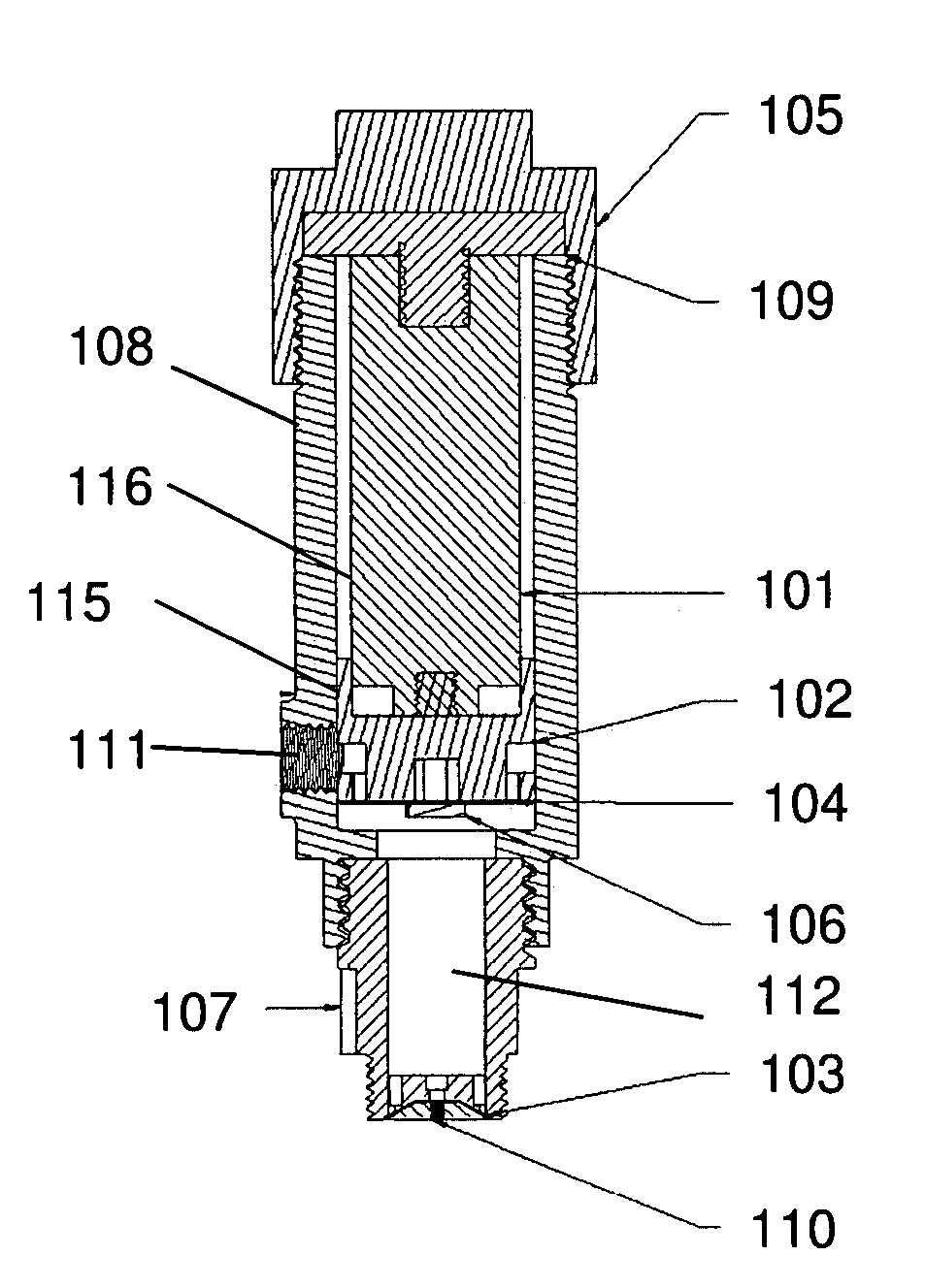
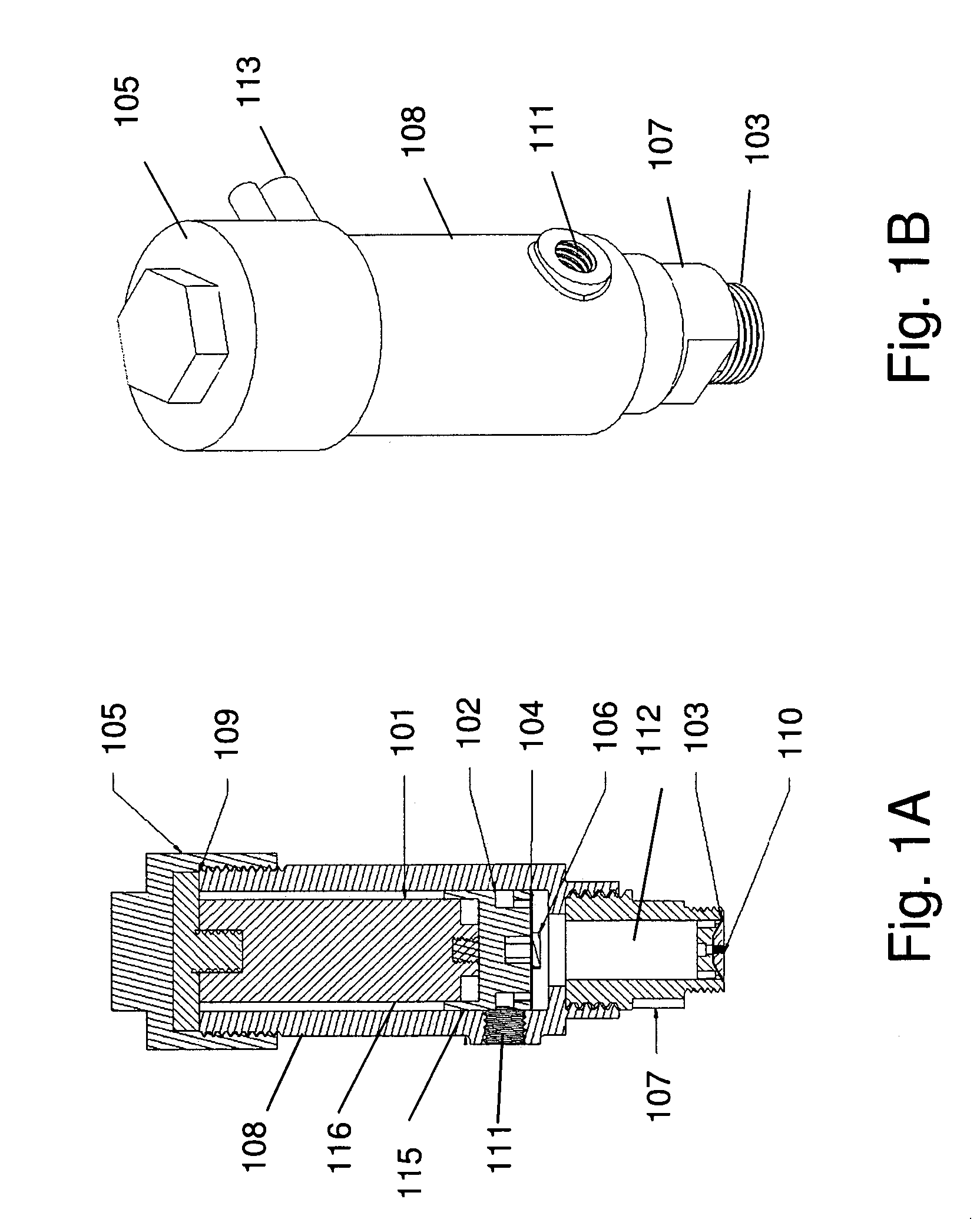
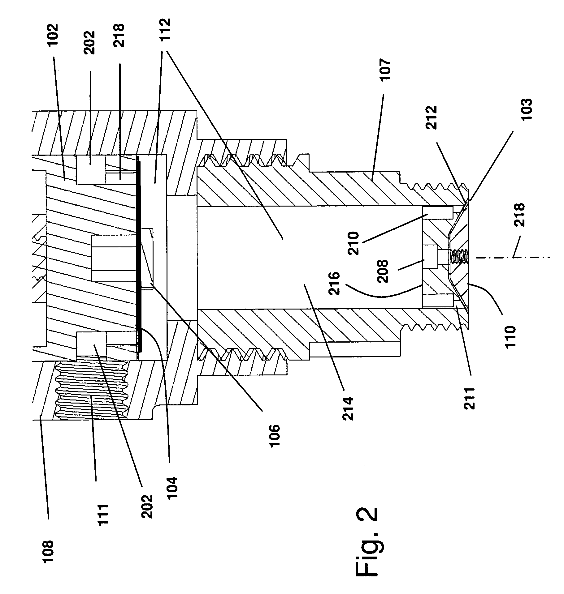
[0013]In a further feature of the invention, the injector spray nozzle comprises a flexible metal cap having a conical face matching a conical face of the nozzle portion of the injector housing and filling the depression in the injector reed valve, bringing the injector exposure to a substantially continuous level with the cylinder head surface. The injector directly injects fuel at a desired angle into the cylinder, avoiding protrusions within the cylinder subject to carbon deposit buildup.

Problems solved by technology

The systems are well suited to the large diesel engines in trucking, automotive and marine service, however the systems scale poorly for smaller engines or where light weight is needed as in aircraft applications.
The engine ends up with a significant fraction of the total weight invested in the injection system.

Method used


Image

  • High pressure piezoelectric fuel injector
  • High pressure piezoelectric fuel injector
  • High pressure piezoelectric fuel injector

Examples


Embodiment Construction

[0033]The injector of the present invention eliminates the need for large, heavy high-pressure fuel pumps while maintaining the fine atomization consistent with the needs of state-of-the-art direct fuel injection systems. The high pressure necessary for the fine atomization is produced by a piezoelectric actuator driven piston. Piezoelectric actuators are found to be exceptionally well suited for very small heavy fuel (VSHF) engine injectors. Piezoelectric actuators may also be referred to as piezoelectric transducers, or PZT's. While the actuation distance of piezoelectric actuators is often small (10-100 micrometers (μm)), the injection volume of injectors designed for very small (i.e. ˜20 cubic centimeters (cc)) engines is also very small 1 to 2 cubic millimeters (1-2 mm3) per stroke at maximum power output. In addition, the piezoelectric actuator is adapted to produce relatively large forces in a compact package, and consequently, are able to create high pressures on the order o...


PUM


Abstract

A combined injector and fuel pump suitable for high pressure direct injection of heavy fuels into Diesel engines, in particular small light weight Diesel engines as may be used in small aircraft. The injector utilizes a piezoelectric actuator driving a piston assembly comprising an inlet reed check valve disposed thereon. Fuel enters an inlet port coupled to an inlet chamber on a first side of the piston. Piezoelectric actuator contraction transfers fuel from the inlet chamber through the reed valve to the pressurization chamber on a second side of the piston. Piezoelectric actuator expansion drives the piston to pressurize the fuel in the pressurization chamber, which forces open a conical annular valve and nozzle assembly injecting a finely atomized mist of fuel into the cylinder.

Description

RELATED APPLICATIONS[0001]This application claims the benefit under 35 USC 119(e) of provisional application Ser. No. 61 / 081,174, Titled “Fuel Injector”, filed Jul. 16, 2008 by Harwood. All of the above listed U.S. Patent and Patent Applications are hereby incorporated herein by reference in their entirety.FIELD OF THE INVENTION[0002]The present invention pertains generally to the field of internal combustion engines, more particularly to the field of fuel injection systems for internal combustion engines.BACKGROUND OF THE INVENTION[0003]Typical injectors for a Diesel engine operate in conjunction with a heavy, high pressure pump to operate the injector. The systems are well suited to the large diesel engines in trucking, automotive and marine service, however the systems scale poorly for smaller engines or where light weight is needed as in aircraft applications. As engine size decreases, the injectors and injector pump do not scale proportionately. The engine ends up with a signif...

Claims


Application Information

Patent Timeline
IPC IPC(8): F02M37/08
CPCF02M57/027F02M61/08F02M61/047F02M2200/21
Inventor HARWOOD, MICHAEL R.
Owner HARWOOD MICHAEL R
Learn More