Cooking stove

a stove and cooking technology, applied in the field of cooking stoves, can solve the problems of reducing the heating efficiency of combustion gas, so as to prevent the temperature decline of combustion gas, improve heating efficiency, and maintain the jetting speed fast

Inactive Publication Date: 2010-05-25
PALOMA IND LTD
View PDF32 Cites 22 Cited by
  • Summary
  • Abstract
  • Description
  • Claims
  • Application Information

AI Technical Summary

Benefits of technology

[0048]As the result of these, high heating efficiency is obtained.
[0069]Furthermore, it is possible to prevent the cooking environment from being deteriorated by heat dissipation from the trivet.

Problems solved by technology

As a result, the combustion gas heat is dissipated through the trivet ring 21, which has been a problem.
Accordingly, as the flame is cooled down by the trivet claws 22 to deteriorate the combustion property, carbon monoxide gas generates, which has been another problem.
Moreover, since the trivet claws 22 are heated up by the combustion flame, the durability of the trivet 20 is lost, and there is a fear of a burn injury to its user, which has been still another problem.
Further, since the ring shaped combustion gas route has a cross sectional area which increases toward the outside, the speed of the combustion gas in the combustion gas route becomes slower, so that the heat flow is dissipated toward the outside.
As a result, in the conventional cooking stoves, the heat flow is dissipated more at the outside in the ring shaped combustion gas route and sufficient heat exchange cannot be made.
On the other hand, in the cooking stove wherein a natural combustion type burner that supplies air necessary for combustion by natural draft force is used, if the distance between the bottom surface of the cooking container P and the burner 14 is made short, and the combustion space is made narrow, the draft force is not formed and the supply and discharge of combustion air cannot be made smoothly.
Therefore, there is a limitation to make the combustion space narrow, which means that the distance between the burner 14 and the cooking container P becomes wide, so that the contact area of the combustion flame and the bottom surface of the cooking container P cannot be increased.
Further, since the combustion space must be made wide, the combustion heat is dissipated unnecessarily in the combustion space, and the combustion heat is cooled down by ambient air flowing into the combustion space.
Consequently, desired heating efficiency cannot be obtained.
Furthermore, even if the combustion gas flow is controlled so that the combustion gas is efficiently guided to the cooking container P for the purpose of improving the heating efficiency, it is difficult to control the combustion gas flow by only the natural draft force.
Accordingly, before the combustion heat is transmitted to the cooking container P sufficiently, the combustion gas is discharged to the outside, and there is a limitation in improvement of heating efficiency.
Thus, the heat transmission of the combustion gas to the cooking container has not been achieved.
As a result, it has been impossible to obtain high heating efficiency.

Method used


Image

  • Cooking stove
  • Cooking stove
  • Cooking stove

Examples


first preferred embodiment

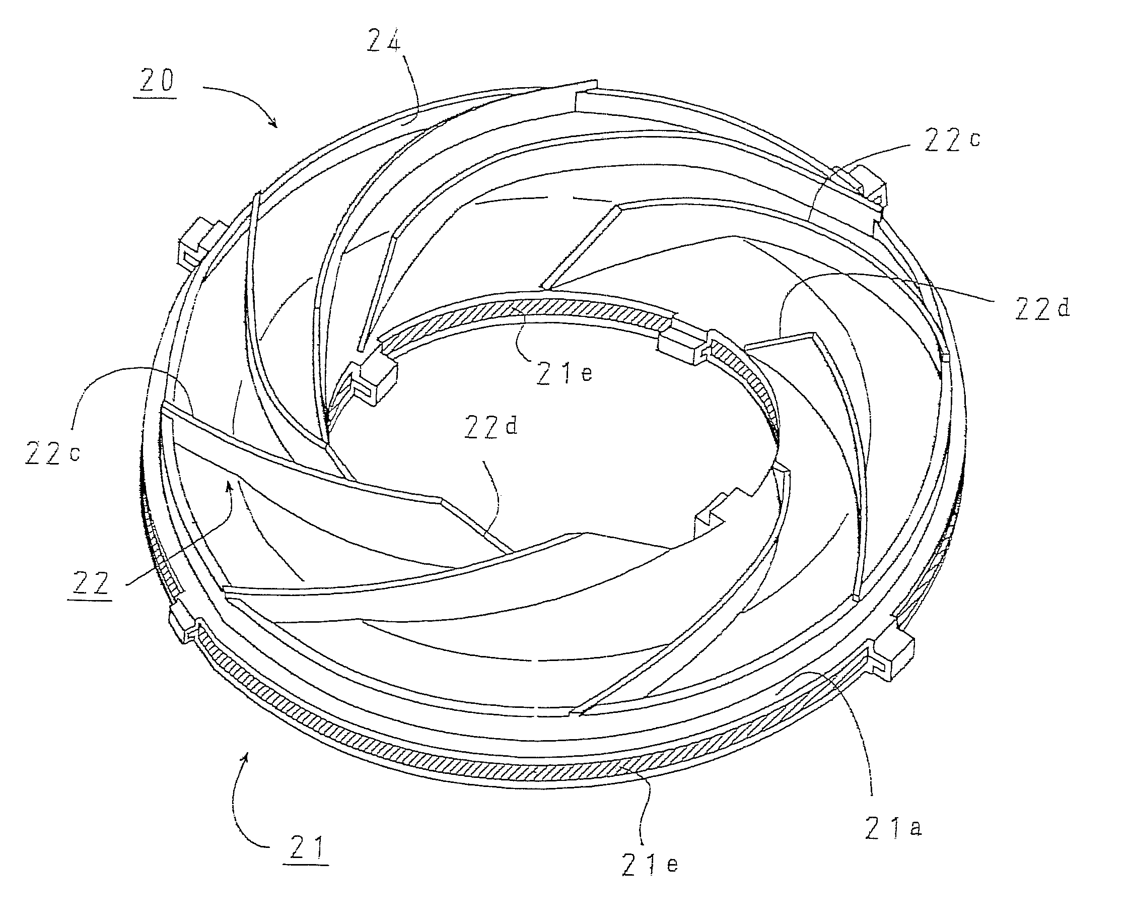
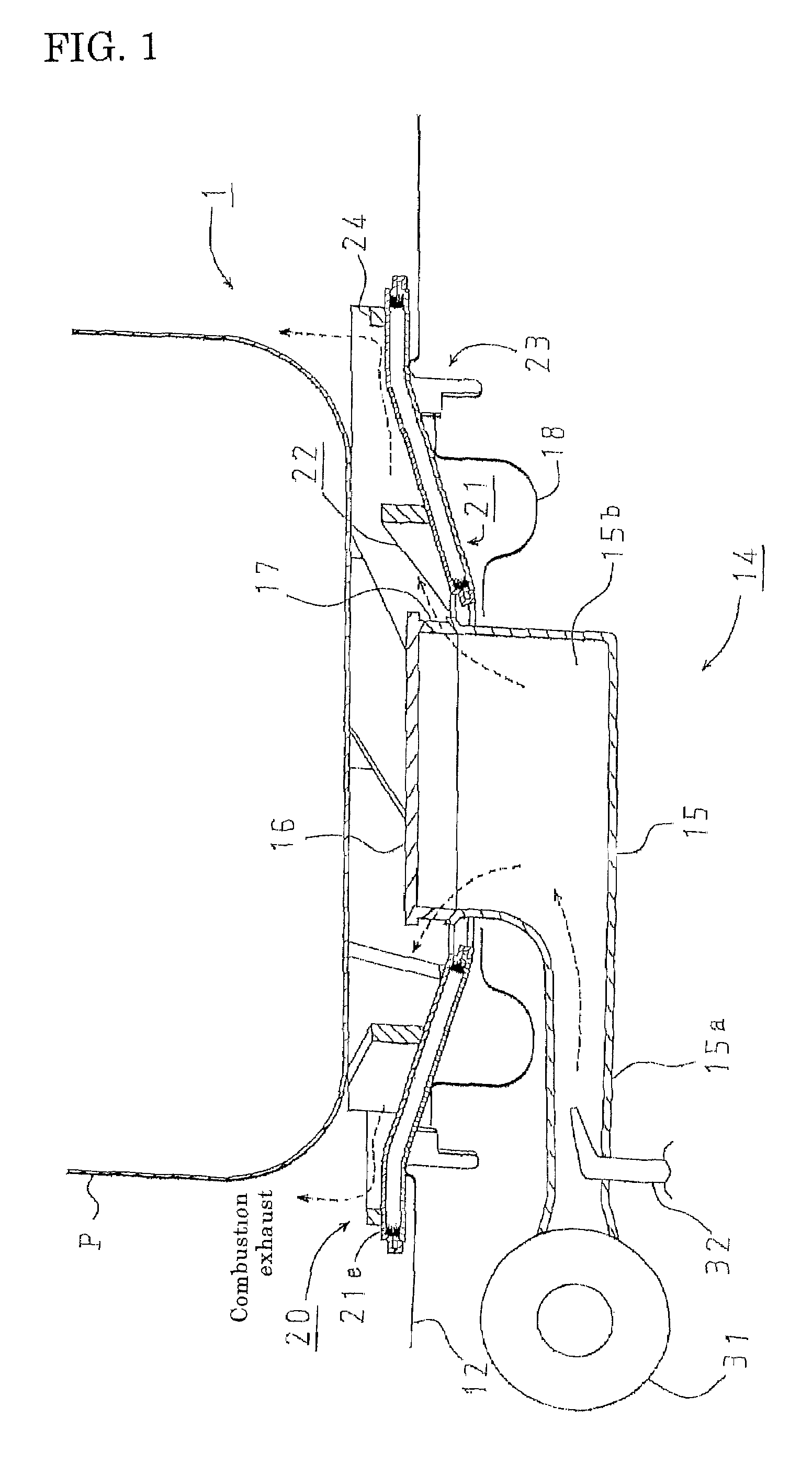
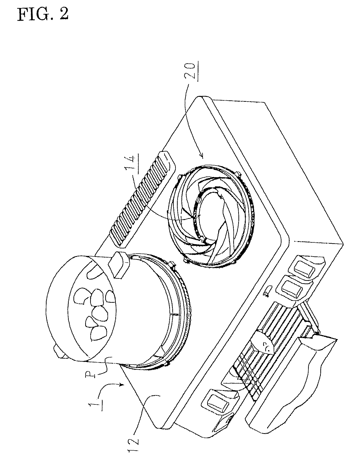
[0089]In a gas table 1 as a cooking stove, as shown in FIG. 1 and FIG. 2, an opening is arranged in a top plate 12, and at the center position of the opening, a cylindrical burner 14 is arranged, and a drip plate 18 is put around the burner. Above around the burner 14, a trivet 20 for putting a cooking container P thereon is arranged.

[0090]The burner 14 is an all primary air type burner that takes in almost of all the air necessary for combustion as primary air, and has a burner main body 15 that mixes fuel gas and combustion air, and a burner head 16 that is put onto the burner main body 15.

[0091]In the burner main body 15, at the upstream end, an air supply fan 31 for supplying combustion air is connected, and in the course of the air supply route, a gas nozzle 32 that jets out fuel gas is arranged. At the downstream of the gas nozzle 32, a mixing pipe 15a for mixing the fuel gas and the combustion air is formed. Further, at the head of the burner main body 15, a cylindrical mixin...

second preferred embodiment

[0137]Next, a gas table according to a second preferred embodiment is explained hereinafter. Meanwhile, portions different from the first preferred embodiment are explained, and an identical code is allotted to the point duplicated with the first preferred embodiment, and explanations thereof are omitted.

[0138]In the gas table 1 according to the second preferred embodiment, with regard to the shape of the trivet claws to load the cooking container thereon, as shown in FIG. 8 through FIG. 10, an arc portion 22e is arranged between the inclined portion 22d and the cooking container loading portion 22c.

[0139]The upper end surface of the arc portion 22e is arranged so as to become higher from the inside end to the external direction, and is concaved downward.

[0140]In general, the cooking container P is round at the bottom.

[0141]In the case where the cooking container P having a round bottom surface is put on the cooking container loading portion 22a of the trivet claws 22 whose upper e...


PUM


Abstract

According to a gas table 1, combustion gas (including the flame) is jetted from a flame port 17 of a burner 14 diagonally upward entirely twisted in the burner circumferential direction. The combustion gas flows into plural combustion gas routes sectioned into spiral shape, and hits trivet claws 22, and goes through. That is, the combustion gas is guided in spiral shape by the trivet claws 22, and exhausted along a cooking container P bottom surface toward the outer circumferential direction. As a result, in the combustion gas route, the combustion gas is always subject to direction changing force and the flow thereof is disturbed, and accordingly, a heat transmission border film is unlikely to be formed on the cooking container P bottom surface, and the heat of the combustion gas is transmitted to the bottom surface of the cooking container P preferably.

Description

[0001]This is a Continuation Application of PCT Application No. PCT / JP2005 / 010421 with an international filing date of Jun. 7, 2005.[0002]This application is based upon and claims the benefit of priority from prior Japanese Patent Application No. 2004-330650 filed on Nov. 15, 2004, the entire contents of which are incorporated by reference.BACKGROUND OF THE INVENTION[0003]1. Field of the Invention[0004]The present invention relates to a cooking stove wherein a cooking container is put on a trivet and heated and cooked by a burner.[0005]2. Description of the Related Art[0006]Conventionally, in the field of cooking stoves, a gas table 1 as shown in FIG. 15 and FIG. 16 has been known. In the gas table 1, a burner 14 of a spontaneous combustion type Bunsen burner is arranged at the center position of an opening arranged in a top plate 12, and a drip plate 18 is put around the burner. A cooking container P is put on a trivet 20 arranged above around the burner 14, and heated by combustio...

Claims


Application Information

Patent Timeline
Patent Type & Authority Patents(United States)
IPC IPC(8): F23H1/02
CPCF24C3/085F24C15/107F23D14/085F23D14/34Y02B40/166Y02B40/00
Inventor KOBAYASHI, TOSHIHIRO
Owner PALOMA IND LTD
Why Eureka
Try Eureka