Refractory metal core main body trench

a technology of refractory metal core and main body, which is applied in the field of refractory, can solve the problems of reducing engine efficiency, reducing cooling effectiveness, and reducing engine efficiency, so as to reduce aerodynamic losses and enhance cooling effectiveness

Inactive Publication Date: 2010-05-25
RAYTHEON TECH CORP
View PDF6 Cites 12 Cited by
  • Summary
  • Abstract
  • Description
  • Claims
  • Application Information

AI Technical Summary

Benefits of technology

[0006]An example article having a film cooling system includes a component wall having a trench recessed therein, a passage that opens into the trench for discharging a coolant flow into the trench and a guide member within the trench for influencing the coolant flow discharged from the passage. In one example, the guide member has a teardrop cross-sectional shape that directs the coolant flow in a predetermined direction to enhance cooling effectiveness. In one example, the article is a turbine blade within a gas turbine engine.
[0007]An example method of film cooling for use in a gas turbine engine includes the steps of discharging the coolant flow from the passage and influencing the coolant flow to flow in a predetermined direction from the passage using the guide member. Optionally, the guide members have a particular orientation relative to an engine centerline axis to reduce aerodynamic losses as the coolant flow flows from the trench over outer surfaces of the turbine blade.

Problems solved by technology

Typical film cooling systems have the problem that the discharged film mixes with a hot gas flow over the surfaces to thereby reduce cooling effectiveness.
One solution is to increase the discharge flow of the air from the passages, however, this requires an increase in air taken from the air flow through the engine, which reduces efficiency of the engine.
Again, increasing the discharge flow of the air would provide more effective cooling over a longer distance, but at the cost of reducing engine efficiency.

Method used


Image

  • Refractory metal core main body trench
  • Refractory metal core main body trench
  • Refractory metal core main body trench

Examples


Embodiment Construction

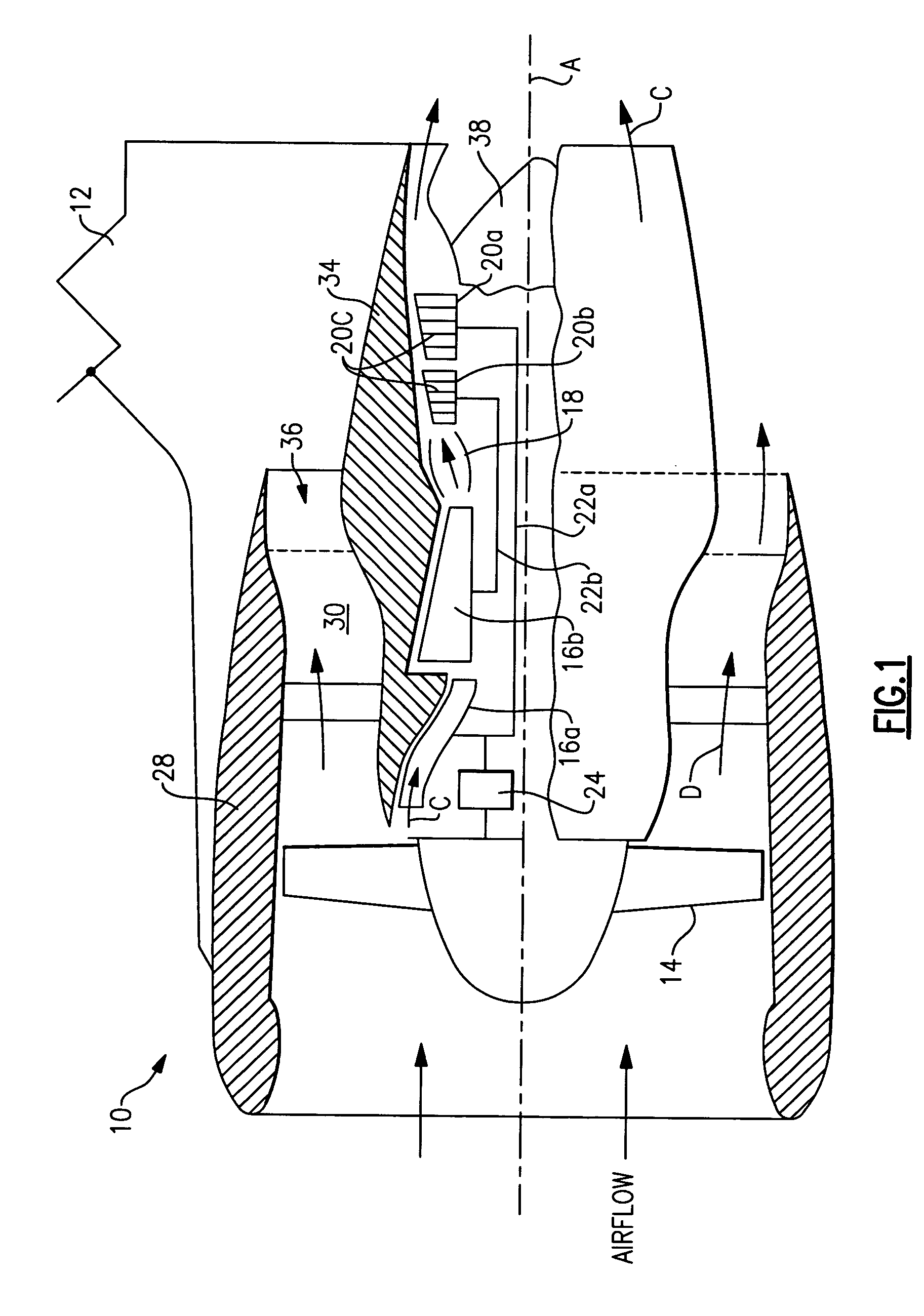
[0014]FIG. 1 illustrates a schematic view of selected portions of an example gas turbine engine 10 suspended from an engine pylon 12 of an aircraft. The gas turbine engine 10 is circumferentially disposed about an engine center line axis A and includes a fan 14, a low pressure compressor 16a, a high pressure compressor 16b, a combustion section 18, a low pressure turbine 20a, and a high pressure turbine 20b. As is known, pressurized air from the compressors 16a, 16b and is mixed with fuel and burned in the combustion section 18 for expansion in the turbines 20a, 20b. The turbines 20a, 20b are coupled for rotation with, respectively, rotors 22a and 22b (e.g., spools) to rotationally drive the compressors 16a, 16b and the fan 14 in response to the expansion of gases over turbine blades 20c of the turbines 20a and 20b. In this example, the rotor 22a drives the fan 14 through a gear 24, such as a planetary gear arrangement or other gear system.

[0015]An outer housing, nacelle 28 (also co...


PUM


Abstract

An article, such as a gas turbine engine turbine blade, includes a film cooling system having a trench recessed within a wall of the component, a passage that opens into the trench for discharging a coolant flow into the trench, and a guide member within the trench for influencing the coolant flow discharge from the passage.

Description

BACKGROUND OF THE INVENTION[0001]This invention relates to cooling a component that is used in an elevated temperature environment and, more particularly, to an article and method for increasing effectiveness of cooling the component.[0002]A variety of different machines, such as gas turbine engines, typically include components that operate under elevated temperatures. To resist the elevated temperatures, the components traditionally employ a cooling system. For example, gas turbine engines utilize turbine blades having a film cooling system. Typical film cooling systems include passages within walls of the turbine blade that carry relatively cool air taken from an air flow through the engine. The passages open to outer surfaces of the turbine blade and discharge the cool air as a film over the surfaces to maintain the blade below a certain temperature.[0003]Typical film cooling systems have the problem that the discharged film mixes with a hot gas flow over the surfaces to thereby...

Claims


Application Information

Patent Timeline
Patent Type & Authority Patents(United States)
IPC IPC(8): F01D5/18
CPCF01D5/186F01D5/187Y02T50/67F05D2260/2212Y02T50/676F05D2260/202Y02T50/673Y02T50/60
Inventor CUNHA, FRANCISCO J.
Owner RAYTHEON TECH CORP
Why Eureka
Try Eureka