
Method and system for monitoring and balancing cells in battery packs utilizing optically coupled cell voltage selection signal, cell voltage isolation amplifier, and zener diodes in balancing circuit

a battery pack and optically coupled technology, applied in battery/fuel cell control arrangement, instruments, electric devices, etc., can solve the problems of affecting battery performance, longevity and safety, affecting the performance of cells, and reducing the number of interconnections required, so as to reduce the number of interconnections

Active Publication Date: 2010-05-25
A123 SYSTEMS LLC
View PDF7 Cites 19 Cited by
  • Summary
  • Abstract
  • Description
  • Claims
  • Application Information

AI Technical Summary

Benefits of technology

The system effectively balances cell voltages and temperatures, enhancing the performance, longevity, and safety of lithium battery packs by preventing premature discharge and ensuring all cells operate within safe thresholds, thereby extending the battery pack's operational range.

Problems solved by technology

The way that a battery pack is operated in the field can significantly affect its performance, longevity and safety.
To complicate matters further, manufacturing defects in lithium cells result in some cells that do not hold as much charge as other seemingly identical cells.
Such defective cells are often also the first to hit the upper threshold during charging.
This imbalance between cells limits the effective range of operation of the battery pack, unless the charge is rebalanced during operation of the battery pack.

Method used


Image

  • Method and system for monitoring and balancing cells in battery packs utilizing optically coupled cell voltage selection signal, cell voltage isolation amplifier, and zener diodes in balancing circuit
  • Method and system for monitoring and balancing cells in battery packs utilizing optically coupled cell voltage selection signal, cell voltage isolation amplifier, and zener diodes in balancing circuit
  • Method and system for monitoring and balancing cells in battery packs utilizing optically coupled cell voltage selection signal, cell voltage isolation amplifier, and zener diodes in balancing circuit

Examples


Embodiment Construction

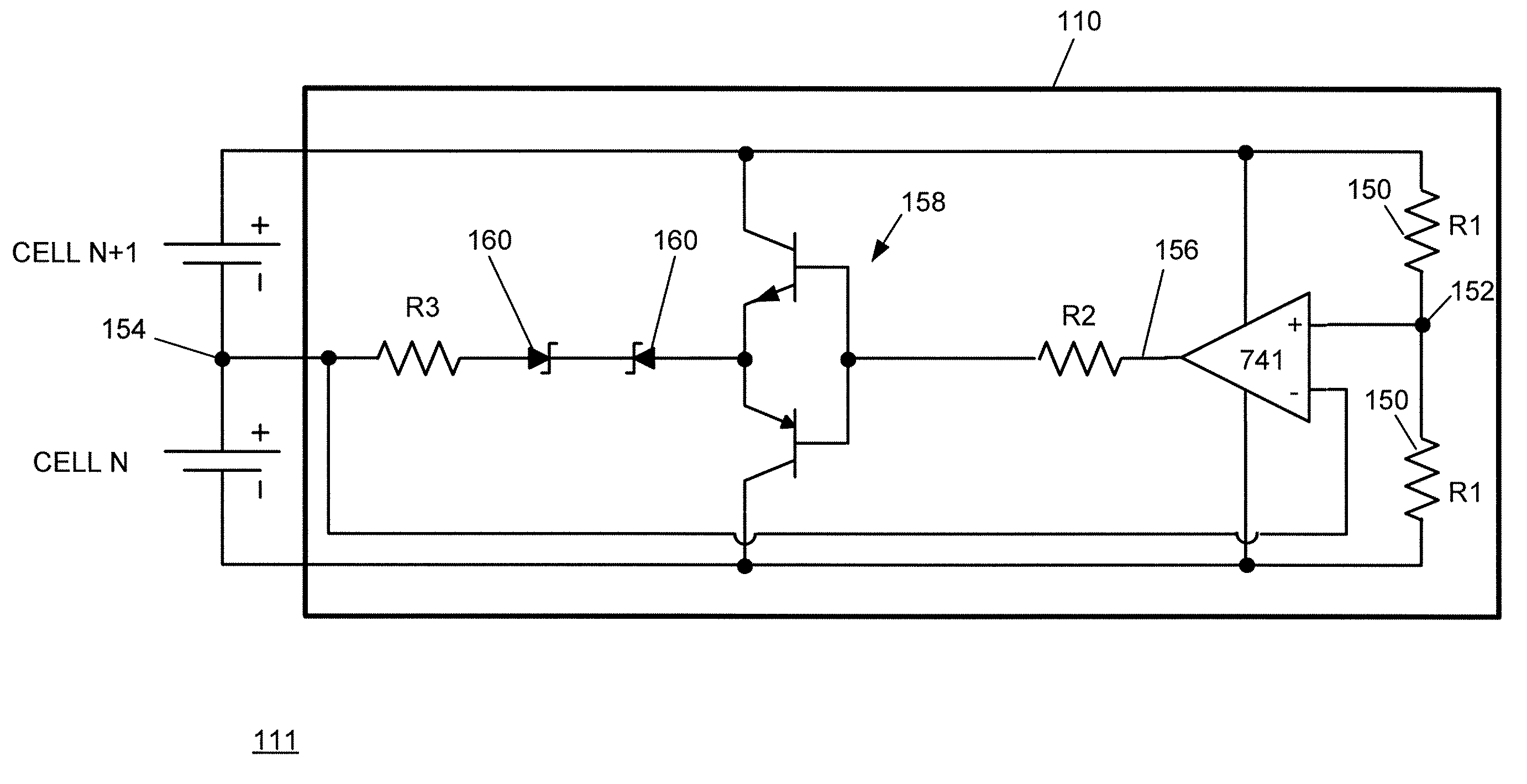
[0039]Embodiments of the present invention are adapted to provide battery cell monitoring, battery cell balancing or temperature monitoring, or combinations thereof. The described embodiments perform signal conditioning required so that safety-critical system voltages and temperatures can safely be sent to an external isolated vehicle controller, which can then make safety critical decisions based on the information received.

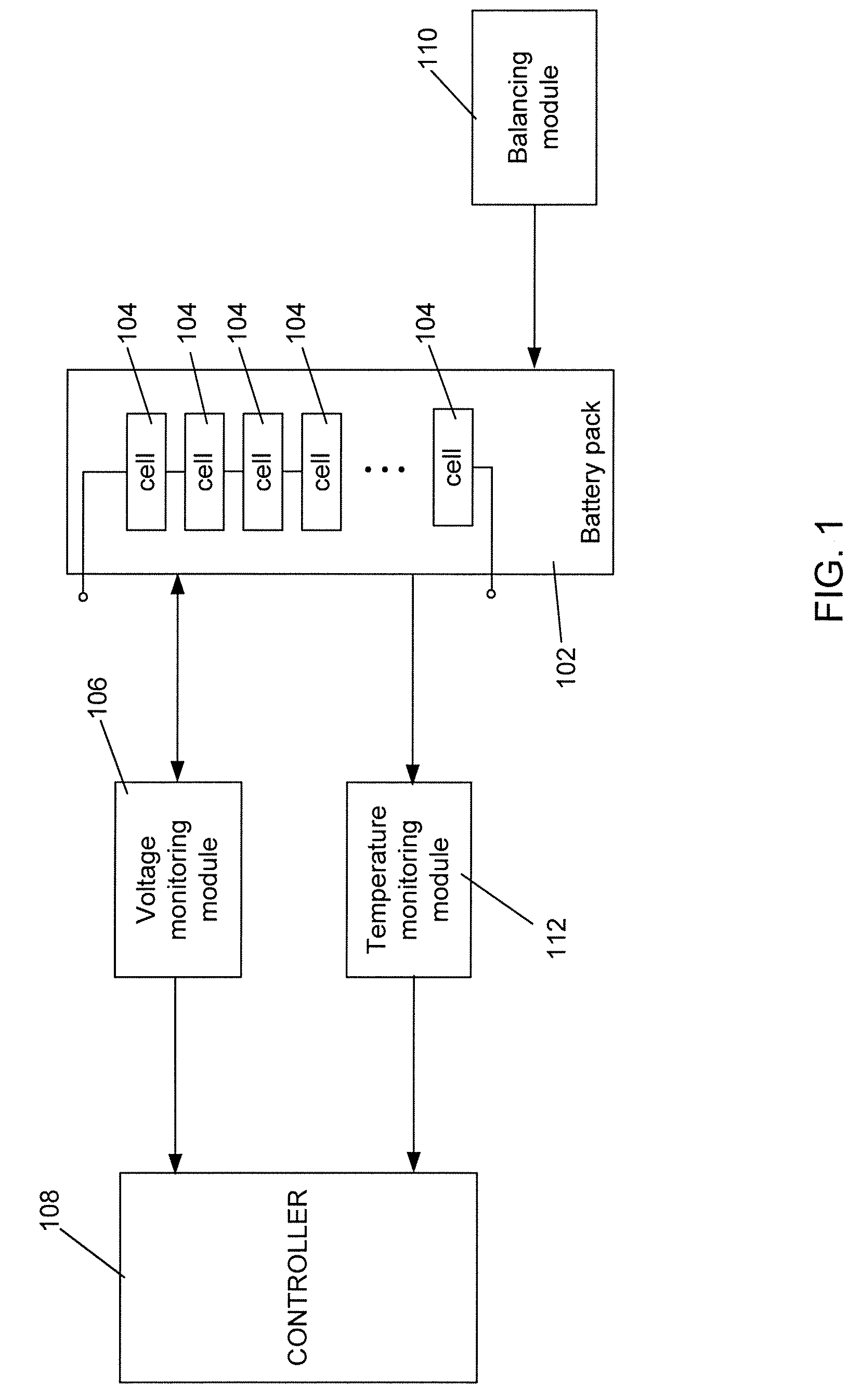
[0040]FIG. 1 is a block diagram illustrating the general functionality provided by one or more of the described embodiments of a system and method for monitoring and balancing battery packs. A battery pack 102 includes a two or more series connected energy delivery devices 104 (e.g., lithium cells).

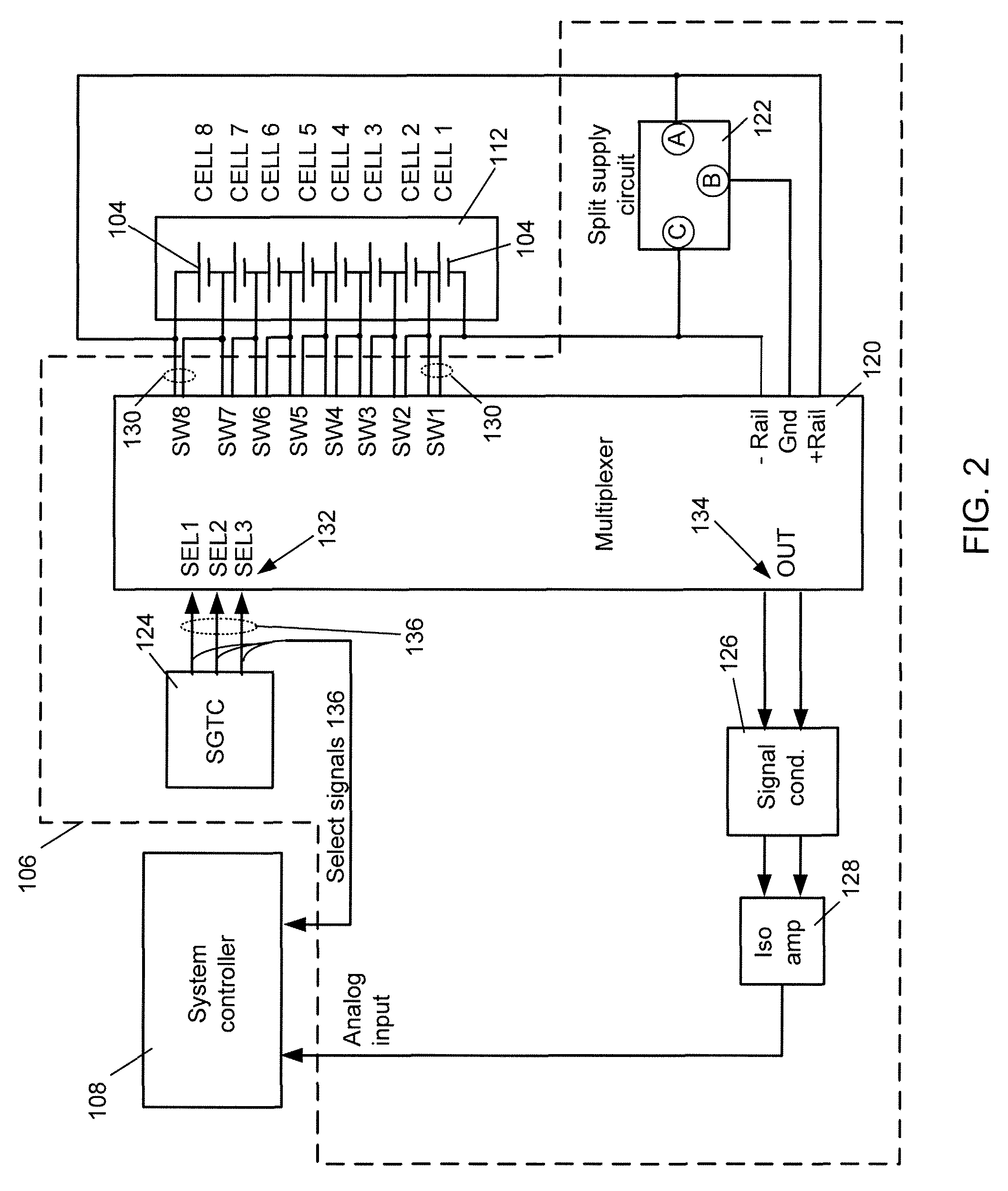
[0041]A voltage monitoring module 106 receives voltage information associated with each of the energy delivery devices 104, conditions and isolates the voltage information and provides the voltage information via an output port to a system controller 108. The system c...


PUM


Abstract

A system for balancing energy delivery devices within the one or more battery packs and for providing isolated monitoring of the battery packs includes at least one group of energy delivery devices electrically connected in series. For each group of energy delivery devices, the system includes a balancing circuit for each adjacent pair of energy delivery devices. The balancing circuit adjusts charge stored in each energy delivery device of the pair so that the charge stored in the energy delivery devices of the pair is substantially equal, and the charge stored in each energy delivery device remains above a threshold. The system also includes a voltage monitoring module for sequentially selecting each of the energy delivery devices and providing a voltage associated with the selected device at an output port. The voltage monitoring module uses a low on-resistance differential multiplexer to select each of the energy delivery devices.

Description

CROSS REFERENCE TO RELATED APPLICATIONS[0001]This application claims benefit of the following patent application: U.S. Provisional Patent Application Ser. No. 60 / 807,821, filed Jul. 19, 2006.BACKGROUND OF THE INVENTION[0002]The present invention relates to methods and systems for operating battery packs, and more particularly, to operating battery packs that are deep cycled in electric vehicle applications, in a manner that enhances performance, longevity and safety.[0003]The way that a battery pack is operated in the field can significantly affect its performance, longevity and safety. This concern is particularly relevant for demanding applications, such as use in electric vehicles.[0004]By way of example, consider a battery pack that is formed from a number of lithium cells connected together in series. The lifetime of the lithium battery pack degrades dramatically if the voltage across one of its cells falls below a predetermined threshold during discharge (typically three volts...

Claims


Application Information

Patent Timeline
Patent Type & Authority Patents(United States)
IPC IPC(8): H02J7/00
CPCH02J7/0019B60L3/0046B60L3/04B60L11/1853B60L11/1859B60L11/1866Y02T10/7011B60L2210/10B60L2240/549B60L2240/545B60L2240/547Y02T10/7005Y02T10/7061Y02T10/7216Y02T10/7055B60L58/18B60L58/14B60L58/22B60L58/25B60L58/15Y02T10/70Y02T10/72Y02E60/10H01M10/48G01R31/396G01R31/3835
Inventor ZAAG, NADERTOTH, AKOS
Owner A123 SYSTEMS LLC
Learn More