

Liquid crystal panel seal barrier and method of manufacturing the same
a technology of liquid crystal panel and sealant, which is applied in the direction of instruments, non-linear optics, optics, etc., can solve the problems of degrading the display quality of the liquid crystal panel, prolonging the filling time of the liquid crystal material, and unstable liquid crystal orientation state, so as to achieve excellent display quality and maintain the bonding strength of the sealant
- Summary
- Abstract
- Description
- Claims
- Application Information
AI Technical Summary
Benefits of technology
Problems solved by technology
Method used
Image

Examples
embodiment 1
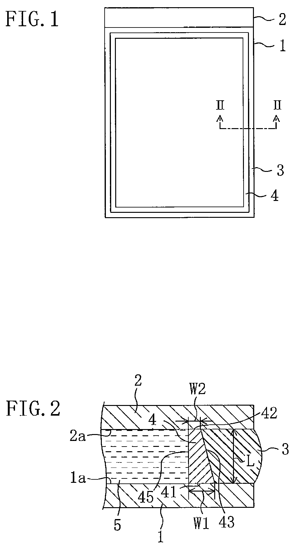
[0045]FIG. 1 is a plan view schematically showing a liquid crystal display device in accordance with Embodiment 1, and FIG. 2 is a sectional view taken along the line II-II in FIG. 1. The liquid crystal display device of the present embodiment includes: a color filter (CF) substrate 1 as a first substrate; a TFT (Thin Film Transistor) substrate 2 as a second substrate opposite to the CF substrate 1; a sealant interposed between the CF substrate 1 and the TFT substrate 2 and formed continuously around the peripheries of the substrates 1, 2; a seal barrier 4 continuously formed in the interior of the sealant 3 along the sealant 3; and a liquid crystal layer 5 surrounded by the seal barrier 4.
[0046]The CF substrate 1 includes a color filter layer (not shown), a transparent electrode made of ITO (indium thin oxide) and others, and a liquid crystal alignment layer (not shown) made of polyimide, polyamic acid, and so on. The liquid crystal alignment layer is normally used after rubbing tr...
embodiment 2
[0066]While the inclined face 43 of seal barrier 4 is flat in Embodiment 1, the inclined face in the present invention is not limited thereto. FIG. 5 is a sectional view schematically showing a seal barrier 4 of Embodiment 2. In the drawings hereafter, the same reference numerals are assigned to elements having substantially the same functions as the elements of the liquid crystal display device in Embodiment 1 for omitting the description thereof.
[0067]The inclined face of the seal barrier 4 shown in FIG. 5 is a convex curved surface 46 protruding toward the sealant 3. Curving of the inclined face toward the sealant 3 provides a light scattering characteristic to the inclined face. Specifically, in curing the uncured sealant by irradiating a ultraviolet ray through the CF substrate 1, part of the ultraviolet ray incident from the bottom face 41 of the seal barrier 4 is incident at the interface between the convex curved surface 46 and the uncured sealant. In incidence, the ultravio...
embodiment 3
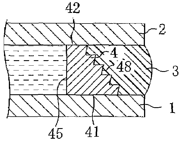
[0069]The convex curved surface 46 as the inclined face provides the light scattering characteristic to the inclined face in Embodiment 2, but the scheme for providing the light scattering characteristic to the inclined face is not limited thereto. In the present embodiment, the inclined face is in a bumpy shape for providing the light scattering characteristic to the inclined face. FIG. 6 is a sectional view schematically showing a seal barrier 4 in a first example of the present embodiment, and FIG. 7 is a sectional view schematically showing a seal barrier 4 in a second example of the present embodiment. The seal barrier 4 shown in FIG. 6 includes a plurality of convex surface 47 protruding toward the sealant 3, and the inclination face of seal barrier 4 shown in FIG. 7 includes a bumpy face 48 in a saw-tooth shape when viewed in section.
[0070]In the present embodiment, similarly to Embodiment 2, the bumpy shape provides the light scattering characteristic to the inclined face, t...
PUM
| Property | Measurement | Unit |
|---|---|---|
| width | aaaaa | aaaaa |
| width | aaaaa | aaaaa |
| width W1 | aaaaa | aaaaa |
Abstract
Description
Claims
Application Information