Method for manufacturing image display device

a technology of image display and resin composition, which is applied in the direction of identification means, instruments, optics, etc., can solve the problems of insufficient curing of photocurable resin composition interposed between such a light-shielding layer and the image display member, and inability to obtain sufficient adhesion for

Inactive Publication Date: 2014-03-06
DEXERIALS CORP
View PDF8 Cites 6 Cited by
  • Summary
  • Abstract
  • Description
  • Claims
  • Application Information

AI Technical Summary

Benefits of technology

[0018]In the method for manufacturing an image display device of the present invention, the ultraviolet rays is irradiated so that the cure rate of the outermost surface of the light-transmitting cured resin layer between the light-shielding layer and the image display member and the cure rate of the entire layer are 90% or more. For this reason, the adhesion strength of the light-transmitting cured resin layer can be maintained even under a heating environment without use of a thermal polymerization process.

Problems solved by technology

For this reason, curing of the photocurable resin composition interposed between such a light-shielding layer and the image display member does not sufficiently proceed.
Therefore, a sufficient adhesion force cannot be obtained.
Accordingly, there have been concerns that positional error between the light-transmitting cover member and the image display member and peeling between them and the photocurable resin adhesion faces occur, and the uncured and remaining photocurable resin composition is impregnated into the light shielding layer to change the color.

Method used


Image

  • Method for manufacturing image display device
  • Method for manufacturing image display device
  • Method for manufacturing image display device

Examples


example 1

[0063]6 Parts by weight of polyisoprene methacrylate (UC102, KURARAY CO., LTD.) as a photocurable resin composition, 15 parts by weight of dicyclopentenyloxyethyl methacrylate and 5 parts by weight of lauryl methacrylate as reactive diluents, 20 parts by weight of polybutadiene (Polyvest110, Evonik Degussa GmbH) as a plasticizer, 1 part by weight of photopolymerization initiator (IRGACURE 184, BASF), and 53 parts by weight of hydrogenated terpene resin (Clearon M105, YASUHARA CHEMICAL CO., LTD.) as a tackifier were uniformly mixed and prepared. The viscosity of the photocurable resin composition (cone-plate rheometer, 25° C., cone and plate: C35 / 2, rotation speed: 10 rpm) was about 6 Pa·s.

(Step (A) (Applying Step))

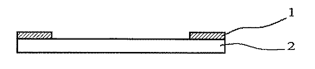
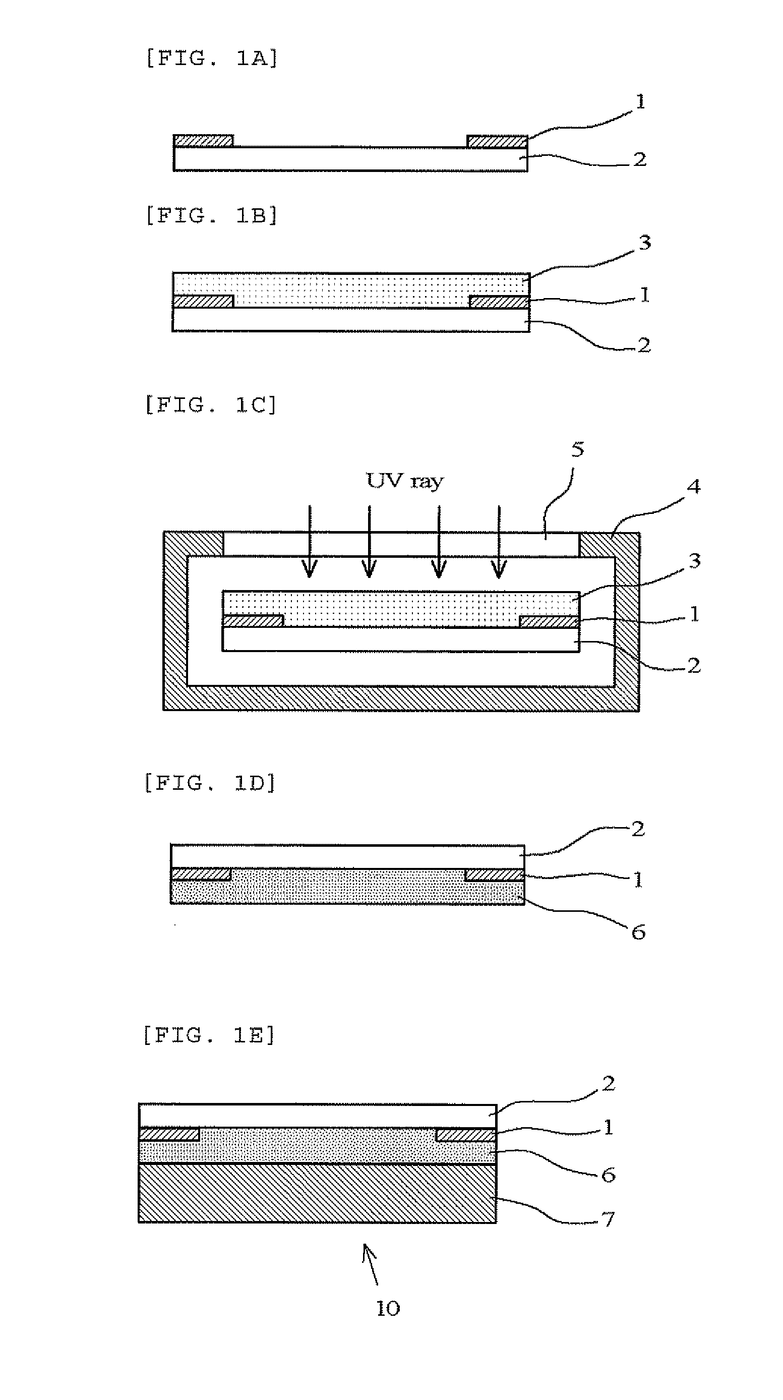
[0064]The photocurable resin composition was then discharged onto a glass plate having a light-shielding layer with a size of 40 (w)×70 (1)×0.4 (t) mm by a resin dispenser, to form a photocurable resin composition film with an average thickness of 200 μm.

(Step (B) (Curing ...

example 2

[0077]A liquid crystal display device and a glass bonded body for measurement of adhesion strength were manufactured in the same manner as in Example 1 except that the degree of reduced pressure inside the chamber was changed to 100 Pa in the step (B) (curing step) of Example 1. The presence or absence of air bubbles was observed and the adhesion state was evaluated. As a result, the cure rate of the outermost surface of the light-transmitting cured resin layer was 92% and the cure rate of the entire light-transmitting cured resin layer was 93%. The evaluation of creep under a heating environment was “A,” and the evaluation of adhesion state under a heating environment was also “A.”

example 3

[0078]A liquid crystal display device and a glass bonded body for measurement of adhesion strength were manufactured in the same manner as in Example 1 except that the pressure inside the chamber was not reduced and the air inside the chamber was replaced with nitrogen in the step (B) (curing step) of Example 1. The presence or absence of air bubbles was observed and the adhesion state was evaluated. As a result, the cure rate of the outermost surface of the light-transmitting cured resin layer was 95% and the cure rate of the entire light-transmitting cured resin layer was 96%. The evaluation of creep under a heating environment was “A,” and the evaluation of adhesion state under a heating environment was also “A.”


PUM


Abstract

A liquid photocurable resin composition not containing a thermal polymerization initiator is applied to a surface of a light-transmitting cover member having a light-shielding layer or a surface of an image display member, irradiated with ultraviolet rays under an atmosphere where the oxygen concentration is significantly decreased and cured, to form a light-transmitting cured resin layer. Subsequently, the image display member and the light-transmitting cover member are stacked through the light-transmitting cured resin layer to manufacture an image display device of the present invention.

Description

TECHNICAL FIELD[0001]The present invention relates to a method for manufacturing an image display device including bonding and stacking an image display member such as a liquid crystal display panel and a light-transmitting cover member such as a transparent protective sheet disposed on the surface side of the image display member, through a light-transmitting cured resin layer.BACKGROUND ART[0002]An image display device such as a liquid crystal display panel used in a data terminal such as a smartphone has been manufactured by placing a photocurable resin composition between an image display member, such as a liquid crystal display panel and an organic EL display panel, and a light-transmitting cover member, irradiating the composition with ultraviolet rays, and curing the composition to form a light-transmitting cured resin layer, thereby bonding and stacking the image display member and the light-transmitting cover member (Patent Literature 1).[0003]A light-shielding layer is pro...

Claims


Application Information

Patent Timeline
Patent Type & Authority Applications(United States)
IPC IPC(8): H01L33/58H01L33/56
CPCH01L33/56H01L33/58G02F1/1333G06F3/041H05B33/10G02F1/1303G02F1/133512G02F2202/28G02F1/133331H10K50/8426H10K50/865H10K50/86H10K71/00G09F9/00G02F1/1335
Inventor HAYASHI, NAOKISHINYA, YOSHIHISAOGAWA, KOUICHINAKAMURA, TSUKASA
Owner DEXERIALS CORP
Why Eureka
Try Eureka