Check patentability & draft patents in minutes with Patsnap Eureka AI!

Magneto-resistive head resistance sensor

a resistance sensor and magnetoresistive head technology, applied in the field of circuits, can solve the problems of reducing the life of the read head, reducing the data bandwidth, and damage to the read head

Inactive Publication Date: 2010-05-25
BROADCOM INT PTE LTD
View PDF5 Cites 0 Cited by
  • Summary
  • Abstract
  • Description
  • Claims
  • Application Information

AI Technical Summary

Benefits of technology

This approach stabilizes the MR bias loop, reduces data corruption, and minimizes write-to-read transition times, enhancing overall system performance by accommodating a wide range of MR resistance values.

Problems solved by technology

However, as track densities increase, mismatch between ideal coil settings for write and read operations due to resonance frequency changes decreases the data bandwidth.
Overbiasing the MR element can cause damage to the read head and reduce the read head's life span.
As shown in equation (1), a higher value of RMR yields a larger loop gain Aloop(DC), which may lead to loop instability.
Otherwise, operation of the MR bias loop interacts with operation of the LCF loop, causing peaking in the frequency response of CCCS reader 200 and possible circuit instability.
Furthermore, if the UGB of the MR bias loop extends to the frequency of data being read from the disk, then the MR bias loop corrupts the read data while attempting to maintain a constant bias across the MR read head.
The risk of overlapping between i) the loop bandwidths of the MR bias loop and ii) the LCF loop setting the fLC, thus interfering with one another, due to variations in RMR increases substantially for larger variation range of RMR.

Method used


Image

  • Magneto-resistive head resistance sensor
  • Magneto-resistive head resistance sensor
  • Magneto-resistive head resistance sensor

Examples


Embodiment Construction

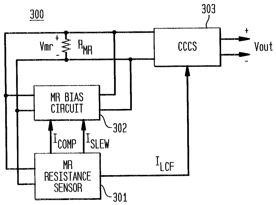
[0048]FIG. 3 shows magneto-resistive (MR) read head (MR reader) portion 300 operating in accordance with one or more embodiments of the present invention. As shown in FIG. 3, MR reader portion 300 comprises an MR resistor RMR, MR resistance sensor 301, MR bias circuit 302, and cross-coupled current sense amplifier (CCCS) 303. CCCS 303 is employed to amplify a signal sensed as current variations through RMR corresponding to data read from, for example, a magnetic recording medium. MR resistance sensor 301 senses an impedance value of RMR, such as a resistance value of RMR, and generates at least one of signals ICOMP, ILCF, and ISLEW, each of which signals is based on the sensed value of RMR. While shown in FIG. 3 as current signals, each of ICOMP, ILCF, and ISLEW might be either a current or voltage signal, either proportional or inversely proportional to the value of RMR.

[0049]In accordance with a first exemplary embodiment of the present invention, the signal ICOMP is employed to p...


PUM

PropertyMeasurementUnit
bias voltageaaaaaaaaaa
voltageaaaaaaaaaa
resistanceaaaaaaaaaa

Abstract

A recording system employing a magneto-resistive (MR) element senses a resistance value of the MR element and generates one or more MR resistance (MRR) signal values based on the sensed MR element resistance value. The MRR signal values might be, for example, current or voltage values proportional or inversely proportional to the MR element resistance value. The MRR signal values might be employed to control one or more of: i) a unity gain bandwidth of a bias loop for the MR element, ii) an MR read head preamplifier low corner frequency, and iii) a slew rate across the MR element.

Description

BACKGROUND OF THE INVENTION[0001]1. Field of the Invention[0002]The present invention relates to circuits for transferring data to and from a recording medium and, in particular, to circuits of a magneto-resistive read head.[0003]2. Description of the Related Art[0004]Conventional recording systems of the prior art encode data and write the encoded data to a recording medium, such as a magnetic hard drive or an optical recording disc. A read channel component is an integrated circuit (IC) of a computer hard disk (HD) drive that encodes, detects, and decodes data, enabling a read / write head to correctly i) write data to the disk drive and ii) read back the data. The encoded data is written to the disc (or other recording medium) by a read / write head. In a magnetic recording system, data is recorded by a head by varying the magnetic field over a bit position (“cell”) on the surface of the recording disc. Data is read by sensing magnetic variations corresponding to the data as the head...

Claims


Application Information

Patent Timeline
Patent Type & Authority Patents(United States)
IPC IPC(8): G11B5/02G11B5/03G11B5/09
CPCG11B5/02G11B2005/0018G11B2005/001
Inventor FITZGERALD, DAVID J.GLEASON, JEFFREY A.HOWLEY, JAMES P.O'BRIEN, SCOTT M.STRAUB, MICHAEL P.
Owner BROADCOM INT PTE LTD
Features
  • R&D
  • Intellectual Property
  • Life Sciences
  • Materials
  • Tech Scout
  • Unparalleled Data Quality
  • Higher Quality Content
  • 60% Fewer Hallucinations
Learn More