Roller for a printer and a method of cooling the roller surface

a technology of rollers and printers, applied in the direction of moving conduit heat exchangers, indirect heat exchangers, lighting and heating apparatus, etc., can solve the problems of reduced cooling capacity, print artifacts, and temperature gradients in axial directions along the surface, so as to reduce the temperature gradient over the rollers and improve cooling efficiency.

Inactive Publication Date: 2010-05-25
OCE TECH
View PDF12 Cites 3 Cited by
  • Summary
  • Abstract
  • Description
  • Claims
  • Application Information

AI Technical Summary

Benefits of technology

[0011]An object of the present invention is to provide a roller that has an improved cooling efficiency by reducing the temperature gradient over the roller.
[0014]The outer tube can include lamellae that extend from the inner surface into the inter tubular space and stretch out along the longitudinal axis of the roller. These lamellae increase the inner surface area of the outer tube, which increases the effective contact area with the flow and thus increases the heat exchange capacity. The blocking element is configured such that it fits in the outer tube and has radial cuts from the outside inwards that allow the lamellae to pass through the blocking element. The size of these radial cuts can be adapted to control the fraction of the flow that is blocked and the fraction that is allowed to continue its path through the inter tubular space.
[0020]It has been observed that for a given air pressure generated by the fan, a higher air flow through the inter tubular space can be realized with this roller system compared to the roller without the blocking element. The present roller system thus also has an improved cooling capacity with respect to the situation without the blocking element.
[0022]In yet another embodiment, the blocking element is not longer than 40 mm in the axial direction. Because there is no air flow for cooling the roller surface at the site of the blocking element, the roller surface temperature can become relatively high at that location. Therefore, it is favorable to keep the axial dimension of the blocking element as low as possible. However, the narrower the blocking element, the stronger the curvature of the ducts, which results in an increased friction of the air flow with the duct walls which hampers the air flow through the blocking element. The axial dimension of the blocking element is therefore a trade-off between realizing a sufficiently high air flow through the roller and minimizing the jump in surface temperature of the roller surface due to the presence of the blocking element.
[0023]In yet another embodiment, the blocking element is constituted of two parts joined by a gasket. The blocking element can, e.g. consist of two discs that entirely or partially divide the inter and intra tubular spaces, and which are joined by a gasket. The ducts that pass through the blocking element are thus segmented into a first and a second part. Every individual disk contains a quarter of a pitch of the duct pairs. Having a blocking element that consists of two separate discs has the advantage that the separate disks are easier to manufacture by, e.g. injection molding. The gasket can be made from, e.g. a metal, a rubber or a plastic sheet and contains holes to connect the corresponding ducts from the first and the second disk constituting the blocking element.
[0024]The two disks constituting the blocking element can also be of approximately the size of the inner tube, and thus only divide the intra tubular space. The gasket can then extend into the inter tubular space to divide the inter tubular space. This embodiment has the advantage that the contact area of the gasket with the outer tube is only very narrow. Therefore the surface area of the roller that is not cooled by the air flow is almost negligible and there is hardly any jump in the surface temperature of the roller.

Problems solved by technology

If the surface temperature rises too high, the toner particles will fuse and stick to the surface of the image-bearing roller resulting in print artifacts.
The disadvantage of the rollers according to the background art is that a temperature gradient is formed in an axial direction along the surface.
This subsequently leads to a reduced cooling capacity of the air flow near the end of the roller which results in a temperature gradient over the roller.
This leads to a relatively inefficient cooling system.

Method used


Image

  • Roller for a printer and a method of cooling the roller surface
  • Roller for a printer and a method of cooling the roller surface
  • Roller for a printer and a method of cooling the roller surface

Examples


Embodiment Construction

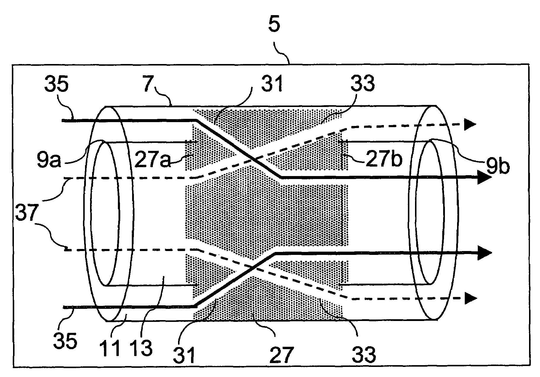
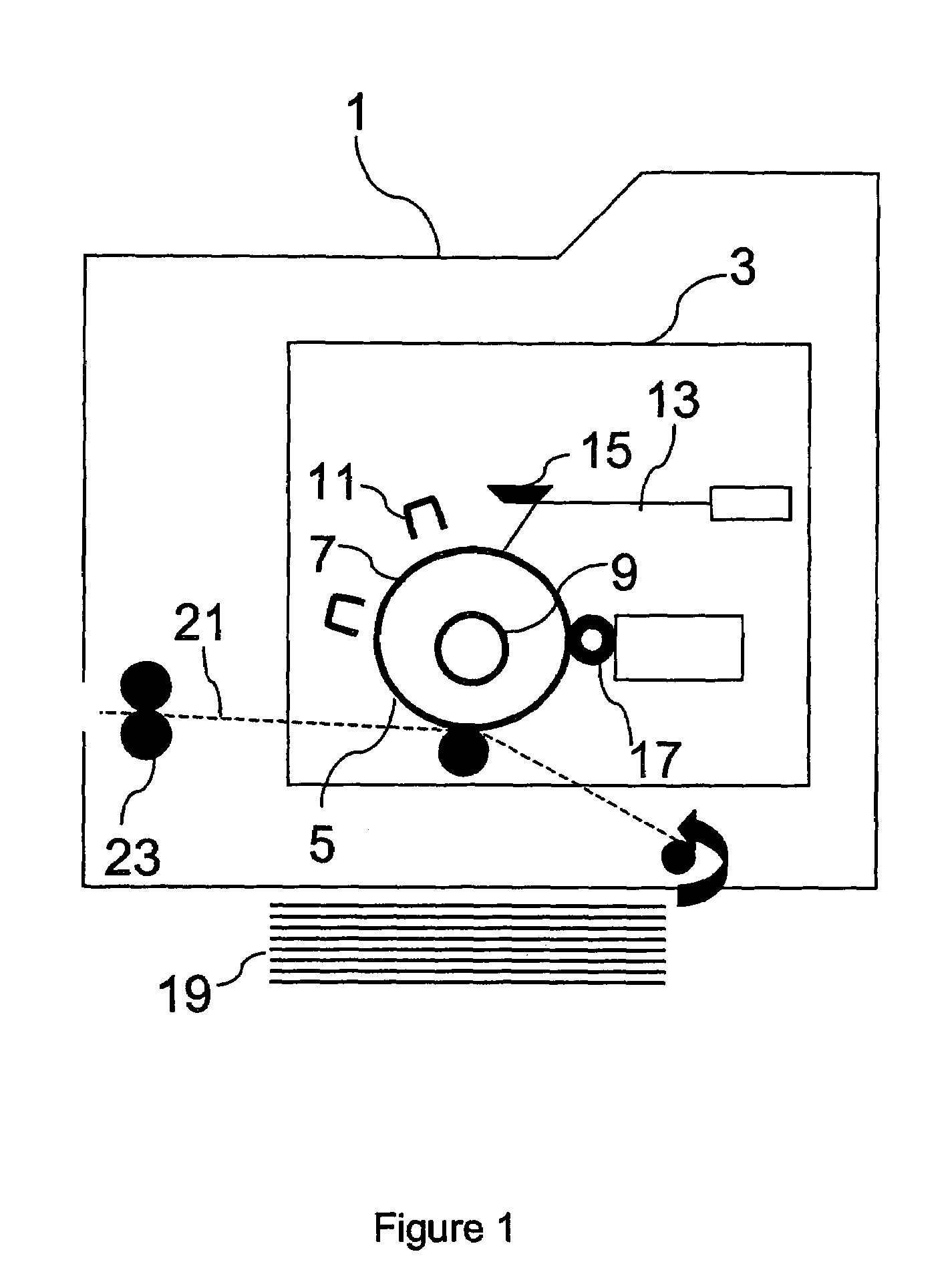
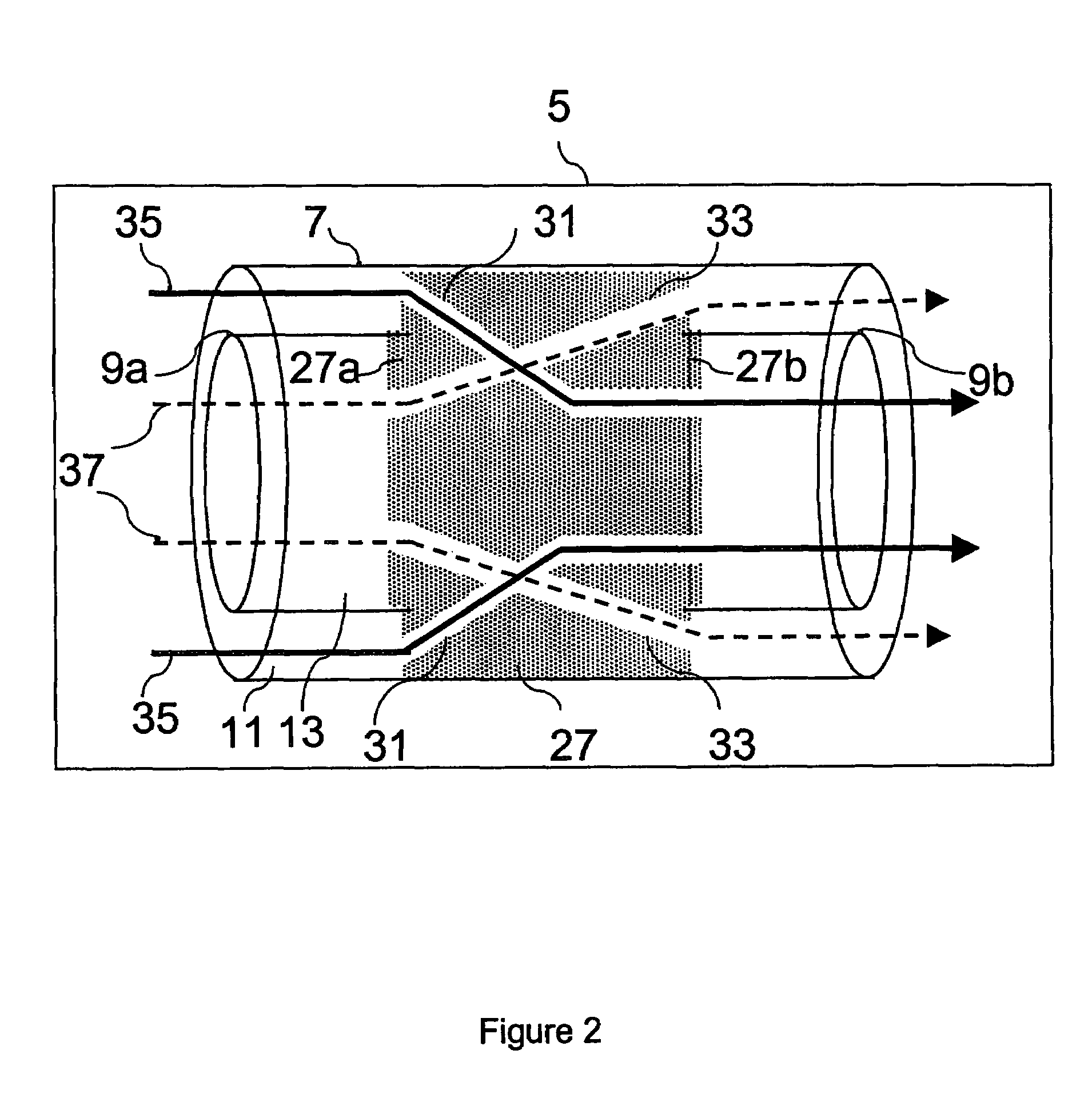
[0032]FIG. 1 shows a schematic drawing of an electrophotographic printer 1. The operation of an electrophotographic printer is known in the background art. The heart of the printer 1 is the print engine 3. The print engine 3 includes an image-bearing roller 5. The image-bearing roller 5 includes an outer tube 7 and an inner tube 9. A photoconductive layer (not shown) is applied on the surface of the image-bearing roller 5. The photoconductive layer which is an insulator in the dark and a conductor when exposed to light. Initially, the photoconductive layer is given a total positive charge by the charge corona wire 11, which is a wire with an electrical current running through it. As the drum revolves, the printer shines a tiny laser beam 13 across the surface to discharge certain points, by reflecting the laser beam on a movable polygonal mirror 15. In this way, the laser “draws” the letters and images to be printed as a pattern of electrical charges, i.e. an electrostatic image. Af...


PUM


Abstract

A roller for a printer includes an outer tube and at least one inner tube. The inner tube is position within the outer tube. The outer tube extends in an axial direction from a first to a second end and the inner tube extends substantially parallel to the outer tube, defining an inter tubular space between the outer and the inner tube and an intra tubular space within the inner tube. The roller also includes a blocking element dividing the inter tubular space and the intra tubular space into a first part extending substantially from the first end to the blocking element and a second part extending substantially from the blocking element to the second end. A first and a second duct connects the first and second part of the inter tubular space with the second and first part, respectively, of the intra tubular space via the blocking element.

Description

CROSS-REFERENCE TO RELATED APPLICATIONS[0001]This nonprovisional application claims priority under 35 U.S.C. §119(a) on Patent Application No. 06115805.1, filed in the European Patent Office on Jun. 21, 2006, the entirety of which is incorporated herein by reference.BACKGROUND OF THE INVENTION[0002]1. Field of the Invention[0003]The present invention pertains to a roller for a printer comprising an outer tube and positioned therein at least one inner tube. The outer tube extends in an axial direction from a first end to a second end and the inner tube extends substantially parallel to the outer tube, defining an inter tubular space between the outer and the inner tube and an intra tubular space within the inner tube.[0004]The present invention also pertains to a printing system including such a roller and a method of cooling the surface of such a roller.[0005]2. Description of Background Art[0006]Such rollers are commonly applied in, e.g. electrophotographic printers. Rollers of thi...

Claims


Application Information

Patent Timeline
Patent Type & Authority Patents(United States)
IPC IPC(8): G03G15/00F24H1/28G03G21/16
CPCG03G21/206G03G15/751F28F5/02G03G2221/1609
Inventor SMEYERS, JOHANNES H. L.CLEVERS, ERNEST J. J.JANSSEN, ROB W. M.VAN HERPEN, WILHELMUS M.
Owner OCE TECH
Why Eureka
Try Eureka