Image-assisted shockwave therapy installation

a technology of image support and installation, which is applied in the field of image-supported shockwave treatment, can solve the problems of time-consuming reconstruction and barely possible displacement of the patient table running horizontal and parallel to the orbital plane operating system, and achieve the effect of sufficient freedom of movemen

Inactive Publication Date: 2010-05-25
SIEMENS HEALTHCARE GMBH
View PDF10 Cites 3 Cited by
  • Summary
  • Abstract
  • Description
  • Claims
  • Application Information

AI Technical Summary

Benefits of technology

[0009]If the carrier device for the shockwave head is arranged in the head direction of the patient with regard to the x-ray C-arm, the doctor has free access to the patient up to the height of the point of the patient to be treated and from the foot region of the patient on the side facing towards the machine such that, for instance, a trans-urethral procedure is possible without hindrance. The inventive arrangement also provides sufficient freedom of movement for an anesthesiologist operating in the head region of the patient.
[0012]In a preferred embodiment the boom is forced to stay in a plane parallel to the orbital plane of the x-ray C-arm. A lateral existing of the focus point of the shockwave head from the orbital plane of the x-ray C-arm is thereby prevented.
[0014]In the normal case, movement of the shockwave head around a specific angle range requires a therapy arc with an at least correspondingly-dimensioned arc length. Given a movement capability of the shockwave head, for example by 250°, a correspondingly-dimensioned therapy arm would significantly overlap a treatment table on the top and bottom and thereby limit the movement freedom of a treating doctor on the treatment side of the patient table. In order to prevent this, in an embodiment the therapy arc is supported such that it can be orbitally displaced. The therapy arc can then be significantly shortened since the maximum travel path of the shockwave head results from the travel length of the therapy arc and the travel length of the shockwave head on the therapy arc. To shorten the therapy arc length it is also conceivable to form this from two arc segments that can be orbitally displaced against one another. Another possibility for arc truncation is to affix the boom on the therapy arc such that the boom can rotate, such that its free end can be pivoted into a position protruding over a free end of the therapy arc.
[0016]In both embodiments, the shockwave head is traversed (penetrated) by a central region that is permeable to x-rays and extends along the shockwave axis of the shockwave head. This embodiment allows a precisely targeted “inline positioning” with the x-ray system without position change of the shockwave head, thus also during a lithotripsy treatment. In a design that is likewise advantageous for both embodiments, the carrier device (together with the shockwave head) can be moved from a treatment position into a park position removed from a patient table or, a patient borne thereupon. The freedom of movement in the space located between x-ray C-arm and head end of the patient table or, respectively, generally in the abdominal region of the patient thus can be increased.

Problems solved by technology

In systems with stationary shockwave head, this requirement can only be satisfied by a position that is uncomfortable for the patient, for example by a prone position, which is particularly uncomfortable for adipose patients.
A disadvantage of this arrangement is that the space circumscribed by the x-ray C-arm is crowded by the carrier device such that a displacement of the patient table running horizontal and parallel to the orbital plane operating system is barely possible.
The result is that the previous spatial orientation must be adapted to the new patient position; for example, a time-consuming reconstruction of auxiliary devices (such as anesthesia devices) must be effected.

Method used


Image

  • Image-assisted shockwave therapy installation
  • Image-assisted shockwave therapy installation
  • Image-assisted shockwave therapy installation

Examples


Embodiment Construction

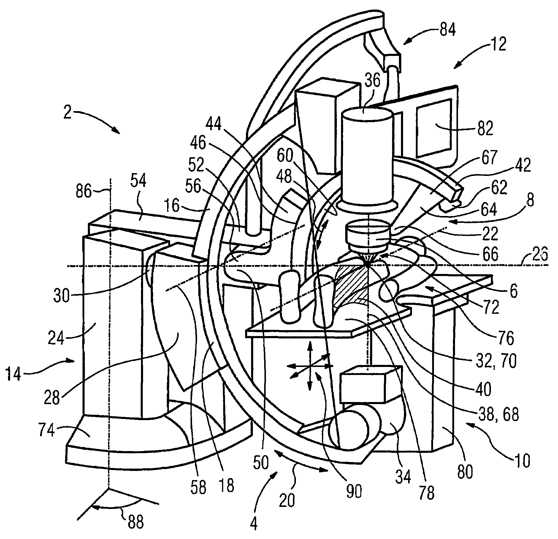
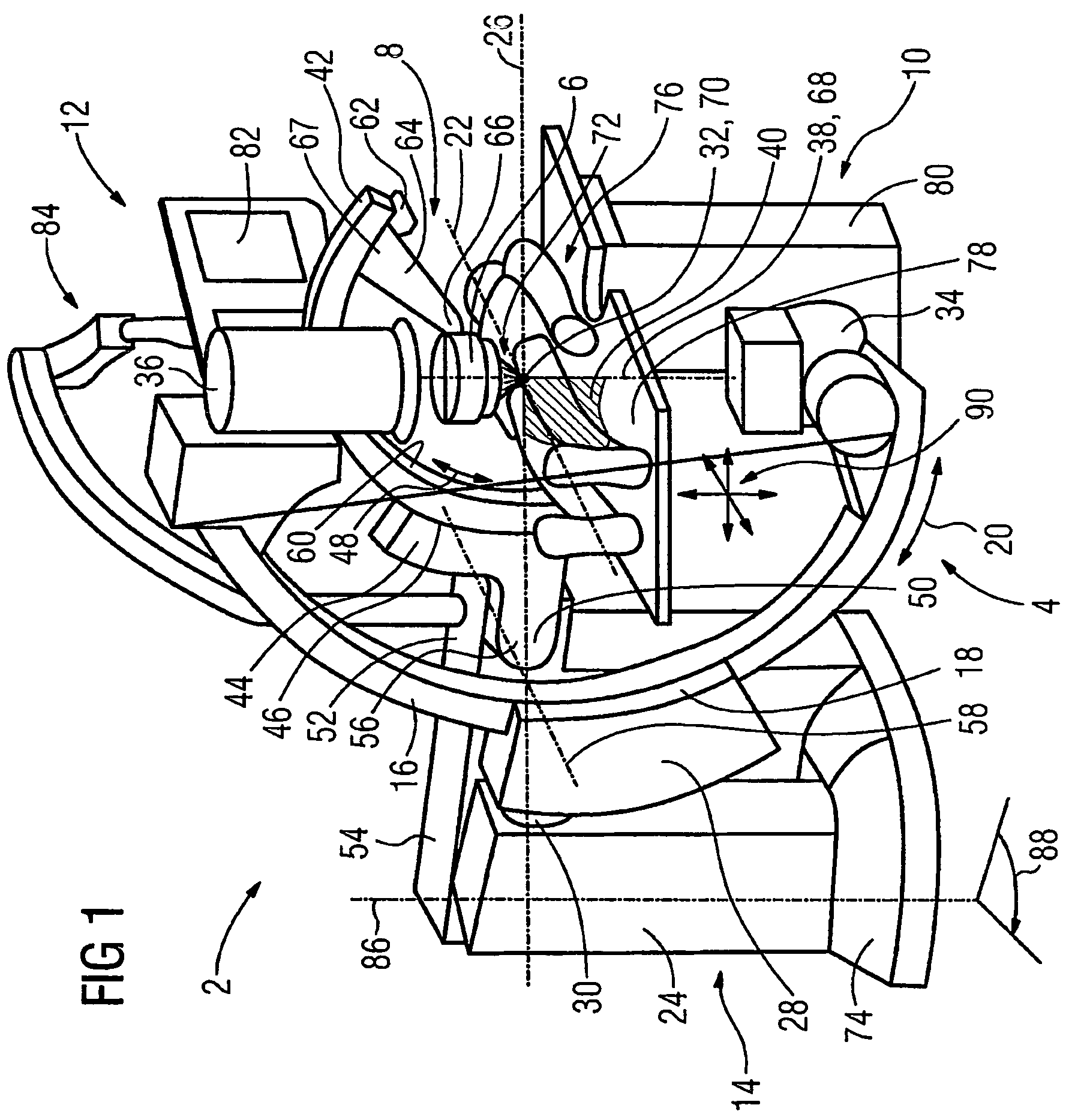
[0024]FIG. 1 shows an SWL system 2 in a first embodiment that has the following sub-components: an x-ray C-arm 4, a therapy C-arm 8 (bearing a shockwave head 6 and characterizing the first embodiment) as a carrier device, a patient table 10 and a display module 12. The x-ray C-arm 4 has a two-part base body 14 on which a C-arm segment 16 is movably supported. A segment-shaped support 18 (not visible) is present in the base body 14 for this purpose, in which support 18 the C-arm segment 16 is forcibly guided, optimally without play. The C-arm segment 16 can therefore be moved one-dimensionally in the orbital direction indicated by the double arrow 20.

[0025]The two-part base body 14 has a base 24 that is stationary at rest. A guide 28 that can rotate around a pivot axis 26 proceeding horizontally is attached on this base 24 via a swivel joint 34. The pivot axis 26 intersects a longitudinal axis 22 at an isocenter 32. The x-ray C-arm 4 can be moved angularly around the pivot axis 26. T...


PUM


Abstract

An installation for image-assisted shockwave therapy has a C-arm x-ray unit that is orbitally movable around an isocenter, and that carries an x-ray imaging system thereon. The installation also has a shockwave head and a carrier device for the shockwave head that is disposed stationarily relative to the x-ray C-arm. A boom that extends toward the x-ray C-arm is carried by the carrier device, the boom having a free end at which the shockwave head is mounted. The boom is movably guided by the carrier device so that the shockwave head is arbitrarily movable to any position and can be arbitrarily aligned to the isocenter within a minimum range of 180° delimited by the top table position and the bottom table position of a patient table.

Description

BACKGROUND OF THE INVENTION[0001]1. Field of the Invention[0002]The invention concerns a system for image-supported shockwave treatment[0003]2. Description of the Prior Art[0004]The main components of a system of the above type are a therapy system and an x-ray system. The therapy system includes a shockwave head that generates ultrasonic waves directed towards a focus point. The primary purpose of such a treatment is the disintegration of kidney and ureter stones. Other applications for treatment of Peyronie's disease or in the field of pain therapy and gastroenterology are also conceivable. The x-ray system serves for location of the stone in the treatment area of a patient and for observation of the treatment success accompanying therapy. It has an x-ray source and an x-ray receiver or image intensifier. Both devices are fixed on the ends of a c-shaped arc (called an x-ray C-arm in the following) that can move orbitally around its isocenter. In the application case the x-ray C-ar...

Claims


Application Information

Patent Timeline
Patent Type & Authority Patents(United States)
IPC IPC(8): A61B5/05A61H1/00A61B17/22
CPCA61B17/2255
Inventor FADLER, FRANZKALTSCHMIDT, RAINERLANSKI, MARKUSPOLSTER, WALTER
Owner SIEMENS HEALTHCARE GMBH
Why Eureka
Try Eureka