Method and device for fitting a machine tool with tools

a technology of machine tools and tools, applied in the direction of metal-working holders, positioning devices, supports, etc., can solve the problems of cost of tools, inability to detect immediate damage, and damage to both tools and workpieces

Inactive Publication Date: 2010-06-01
RICHARD BAHR GMBH FORMEN UND WERKZEUGBAU
View PDF14 Cites 9 Cited by
  • Summary
  • Abstract
  • Description
  • Claims
  • Application Information

AI Technical Summary

Problems solved by technology

If this is not executed in a perfect manner, damage to both tool and workpiece can occur.
Particularly serious are incidences of damage that cannot be immediately detected when they occur.
An extremely important aspect is the cost of the tools.
Thus a carbide milling cutter can, for example, cost several hundred euros.
However, this is exactly what is not always the case.
The economics of the washing process suffer in turn as a result.
However this is not possible in practice, since it is bound up with personnel costs and is completely contrary to the concept of rationalisation.
Also the accuracy of manual adjustments is insufficient.

Method used


Image

  • Method and device for fitting a machine tool with tools
  • Method and device for fitting a machine tool with tools
  • Method and device for fitting a machine tool with tools

Examples


Embodiment Construction

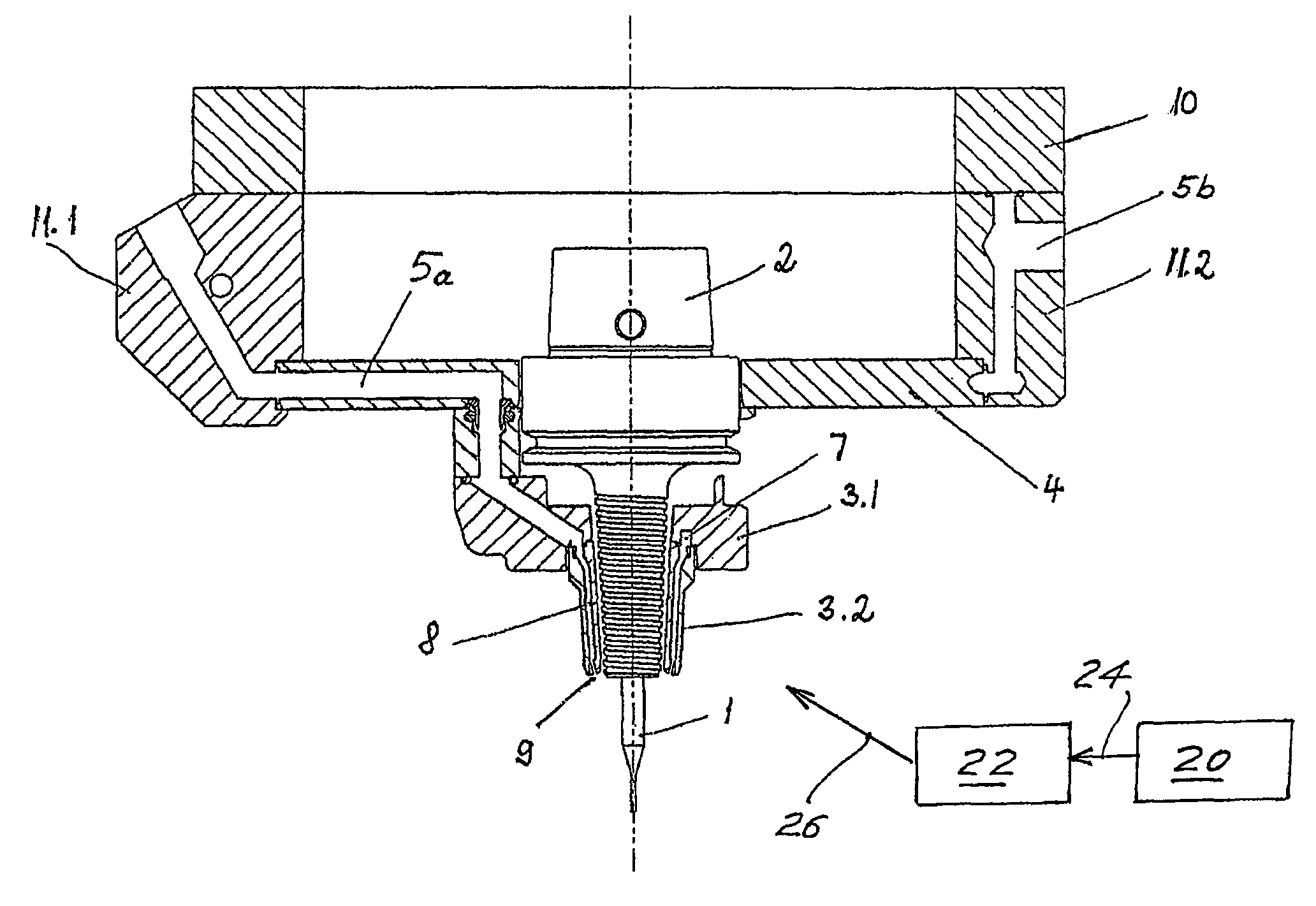
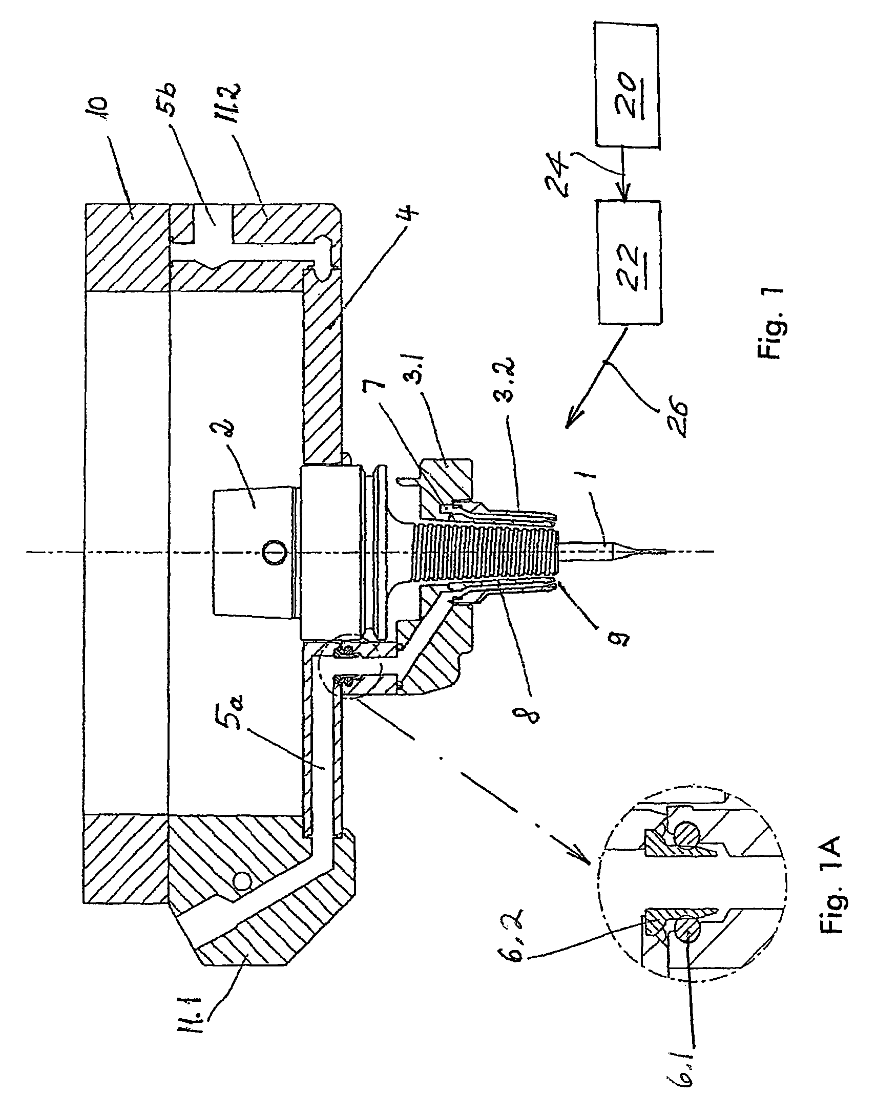
[0022]In FIG. 1 one recognises in detail a tool 1. This can be a milling cutter, or a drill bit, or a reamer, or another tool.

[0023]The tool 1 is clamped in a tool holder 2. The tool holder is fixed to the frame of the machine tool, which is not shown in detail.

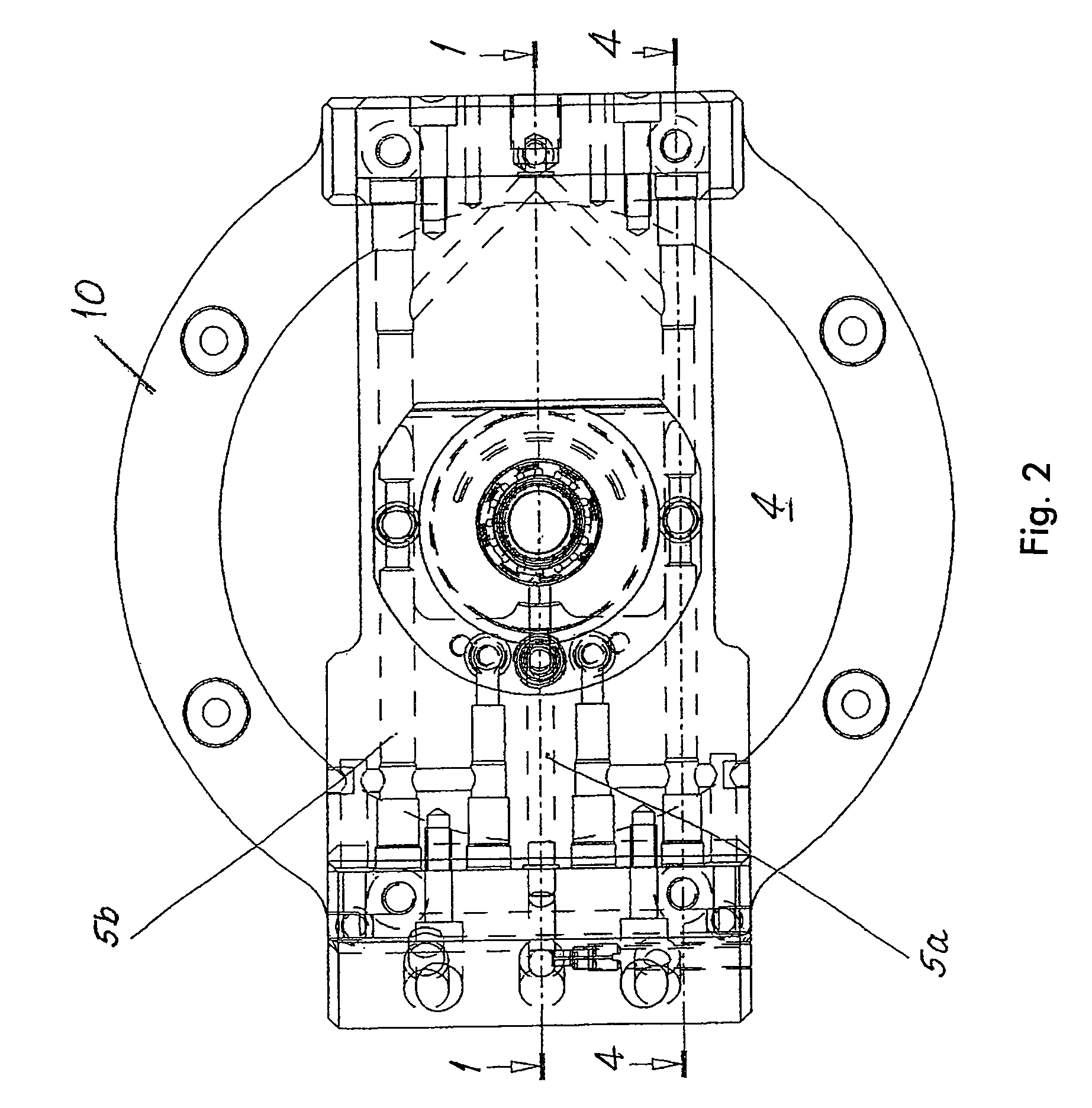
[0024]A nozzle body 3 comprises an upper, cylindrical part 3.1 and a lower truncated cone shaped part 3.2. The nozzle body 3 is fixed to a nozzle plate 4 by means of a latching mechanism, which will be described further below.

[0025]A washing medium is supplied to the nozzle body 3 from above. This is directed into a passage 5a, which extends in the nozzle plate 4 in the horizontal direction. It flows through a valve body 6, then arrives at a horizontal annular passage 7, then into holes 8, which are located in the lower truncated cone shaped part 3.2 of the nozzle body, and exits through the nozzles 9. In the present case the nozzles are circular in cross-section. A large number of nozzles are arranged in a distributed manner...


PUM

PropertyMeasurementUnit
timeaaaaaaaaaa
flow rateaaaaaaaaaa
angleaaaaaaaaaa

Abstract

The invention relates to a method of fitting a machine tool with tools which are cooled by a free-flowing medium during operation of the machine tool, comprising the following method steps: a plurality of various tools are provided in order to carry out successive machining operations on a workpiece; a plurality of various nozzle devices are provided, each of which can be fitted together with a specific tool and connected to a medium source and has such a medium jet geometry that the respective medium jets strike locations where the machining takes place; a specific nozzle device is in each case fitted together with a specific tool and connected to the medium source before the operation of the machine tool is started.

Description

CROSS REFERENCE TO RELATED APPLICATIONS[0001]The present application is a 35 U.S.C. §371 National Phase conversion of PCT / EP2007 / 001069, filed Feb. 8, 2007, which claims benefit of German Application No. 10 2006 006 958.7, filed Feb. 14, 2006, the disclosure of which is incorporated herein by reference. The PCT International Application was published in the German language.BACKGROUND OF THE INVENTION[0002]The invention concerns the machining of workpieces in a machine tool by means of a plurality of machining processes. Here different tools are used for the individual machining processes. The tools come into use one after another. Here not only tools of one and the same category come into consideration, such as for example milling cutters, but also tools of different categories, for example milling cutters, drill bits, and so on.[0003]The tools are stored in a tool magazine. Here this can, for example, take the form of a turntable, on the circumference of which a large number of dri...

Claims


Application Information

Patent Timeline
Patent Type & Authority Patents(United States)
IPC IPC(8): B23Q3/157B23Q11/10
CPCB23Q3/157B23Q11/10Y10T483/19Y10T483/1764Y10T409/304032Y10T483/15Y10T483/1855Y10T408/46Y10T408/44Y10T483/175B23Q11/1084B23Q11/00
Inventor BAHR, RICHARD
Owner RICHARD BAHR GMBH FORMEN UND WERKZEUGBAU
Why Eureka
Try Eureka