
Furniture hinge with damping device

a technology of damping device and hinge, which is applied in the field of furniture hinges, can solve the problems of poor damping device operation, annoying noise, and device drawbacks, and achieve the effects of improving efficiency, improving kinematic motion, and greater silen

Inactive Publication Date: 2010-06-08
ARTURO SALICE
View PDF11 Cites 16 Cited by
  • Summary
  • Abstract
  • Description
  • Claims
  • Application Information

AI Technical Summary

Benefits of technology

The solution effectively reduces noise and improves the smooth operation of doors by increasing friction surfaces and regulating angular velocity, making the damping device compact, easy to produce, and aesthetically integrated within the furniture, while maintaining standard production processes.

Problems solved by technology

However, these devices have some drawbacks.
If the working and coupling tolerances of the components are not sufficiently precise, this can lead to poor operation of the damping device due to irregular behaviour or to possible idle travel of the slider.
In particular, jerks can occur during the return movement, producing an annoying noise that can be heard from the outside.
One solution to the problem, described in document DE10211294, provides for two rotating discs operated by the slider and immersed in a viscous medium, but the damping effect that is obtained is not satisfactory.

Method used


Image

  • Furniture hinge with damping device
  • Furniture hinge with damping device
  • Furniture hinge with damping device

Examples


first embodiment

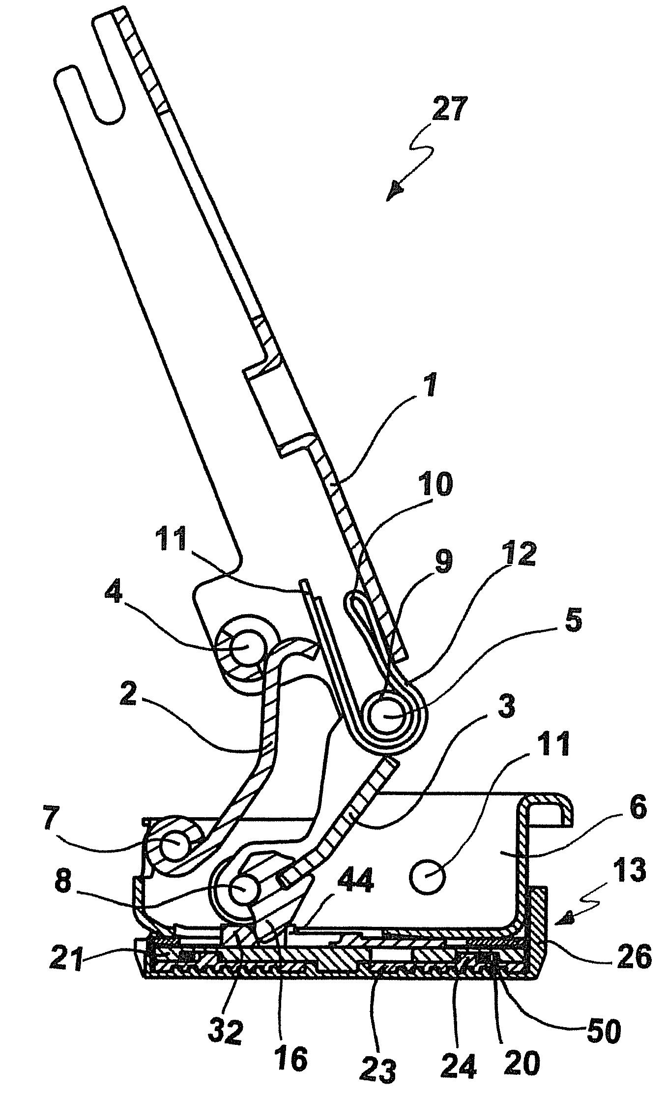
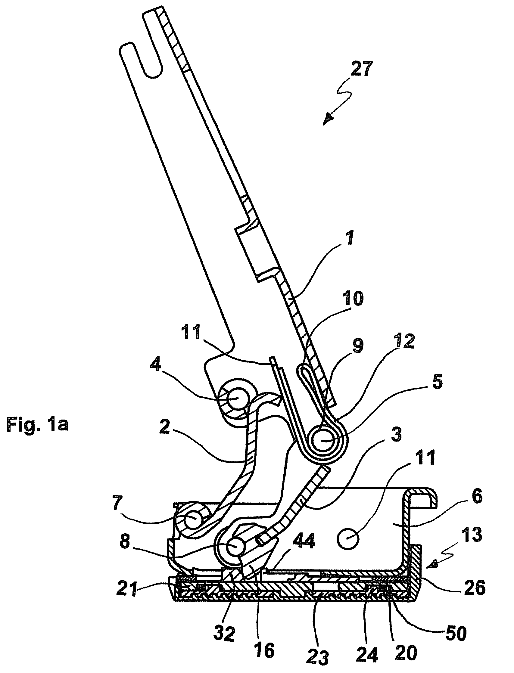
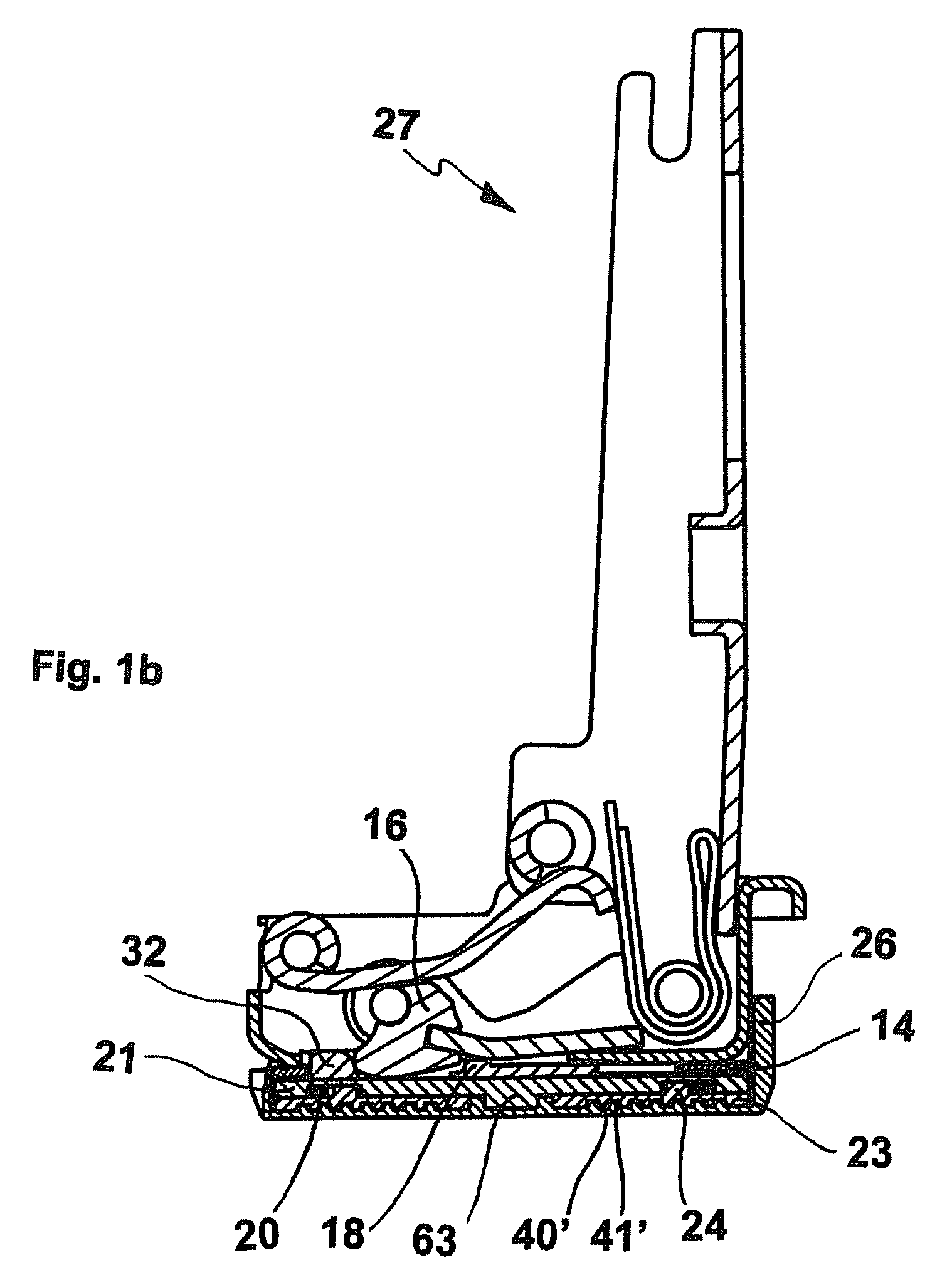
[0030]With reference to FIGS. 1a and 1b, the hinge is represented, indicated as a whole with the reference 27, said hinge comprising a fixed element, or hinge arm 1, which is fixable on a base, or plate, in turn solidarity fixed to a bearing wall of a side panel or any suitable element of a piece of furniture. The hinge is provided with two rockers 2 and 3, with a respective first end thereof pivoting about two respective pins 4, 5 housed in holes in the side walls of the arm 1. The arm 1 is connected to a box element 6, fixed in a cavity produced in the inside wall of the door or wing of the piece of furniture, or of any other appropriate pivoting element of the piece of furniture. The two respective second ends of the rockers 2 and 3 are housed in rotation on two other respective pins 7, 8 with axes parallel to the first two pins 4, 5. The four pins 4, 5, 7, 8 form an articulated quadrilateral.

[0031]Around the articulation pin 5, connecting the rocker 3 to the arm 1, there is prov...

second embodiment

[0053]the invention provides for application of the same damping device 13, in both the alternative embodiments described, to a hinge 27′ with one single articulation pin 8′, shown in FIG. 2.

[0054]Unlike the hinge 27 of the articulated quadrilateral type described previously, the hinges with one single pin are provided with a fixing arm 1′, substantially L-shaped, comprising in a single block the arm 1 and the rocker 3 of the hinge 27, and suitable to pivot about the articulation pin 8′ with the box element 6′. As is known, the rockers 2 and 3 and the other articulation pins 4, 7, 5 are therefore not provided. FIG. 2 shows a torsion spring 103 wrapped around a further transverse pin 104 and provided with an arm 100 which rests on an edge of the connection element 16′, acting as a cam, in order to supply the closing thrust to the hinge. More appropriately, a pair of specular adjacent springs 103 can be provided, the central arms 100 of which passing through a central cavity 101 locat...


PUM


Abstract

Furniture hinge with damping and / or braking device in alternative to those already existing and capable of guaranteeing an improved efficiency during the closing or opening operation of the doors, or other furniture parts, thanks to an improvement of the kinematic motion for transmitting motion from one of the rockers to the damping elements. The improved efficiency of this hinge is also obtained by increasing the friction surfaces with a viscous medium present in suitable areas of the hinge and by allowing regulation of the trend of the angular velocity of a circular shaped element, for example a disc, which acts as braking element in contact with the viscous medium.

Description

FIELD OF THE INVENTION[0001]The present invention relates to a furniture hinge, in particular a hinge with spring for doors, or in general for furniture parts suitable to be brought into motion, provided with a damping device which acts during opening and / or closing of the doors.STATE OF THE ART[0002]Furniture provided with doors or wings to close compartments and which open by pivoting about a horizontal or vertical axis uses various types of hinge. A type which is very widely used today is one in which the hinges to support the doors in the closed position are not visible from the outside of the piece of furniture when the door is closed.[0003]Hinges of this type are today commonly used in the furniture industry as they have a series of advantages, which have determined their extensive use on the market. Some embodiments of known hinges are provided with springs of various types to produce a return force during closing or a pushing force during opening of the doors to which they a...

Claims


Application Information

Patent Timeline
Patent Type & Authority Patents(United States)
IPC IPC(8): E05D7/00
CPCE05D11/1021E05F5/02E05F5/006Y10T16/558E05Y2201/21E05Y2201/254E05Y2201/266E05Y2201/604E05Y2201/622E05Y2600/46E05Y2900/20Y10T16/53607Y10T16/5383Y10T16/2771Y10T16/304Y10T16/53833Y10T16/54028E05Y2800/73E05D3/06E05D11/10
Inventor SALICE, LUCIANO
Owner ARTURO SALICE
Learn More