Composite transmission shaft joint
- Summary
- Abstract
- Description
- Claims
- Application Information
AI Technical Summary
Benefits of technology
Problems solved by technology
Method used
Image
Examples
Embodiment Construction
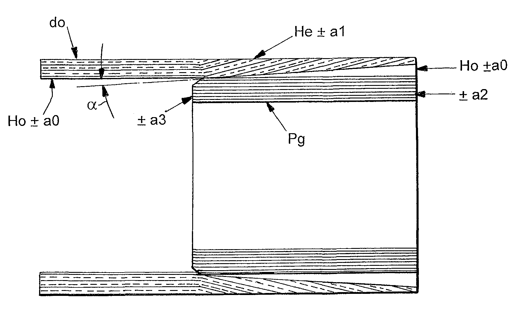
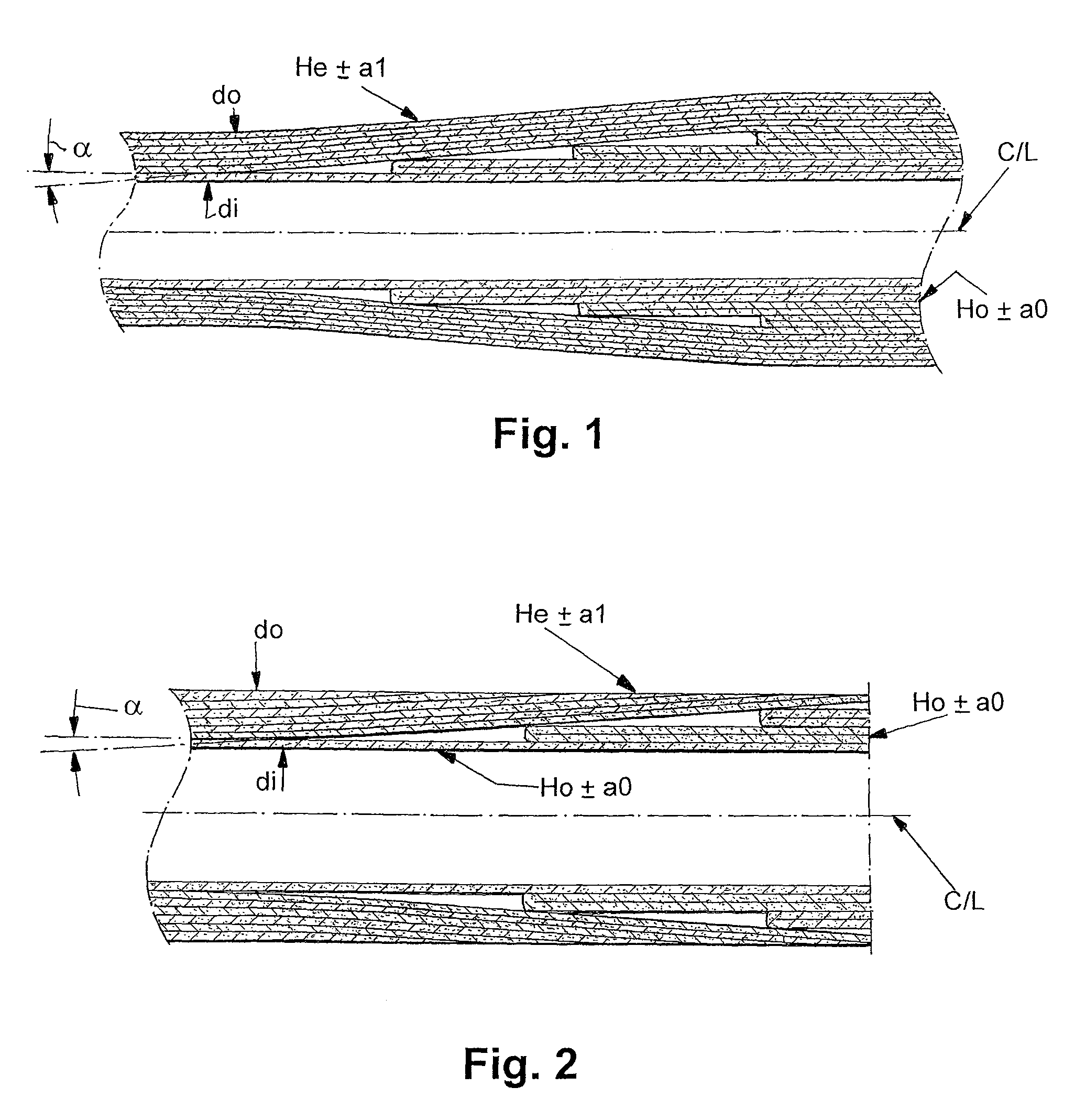
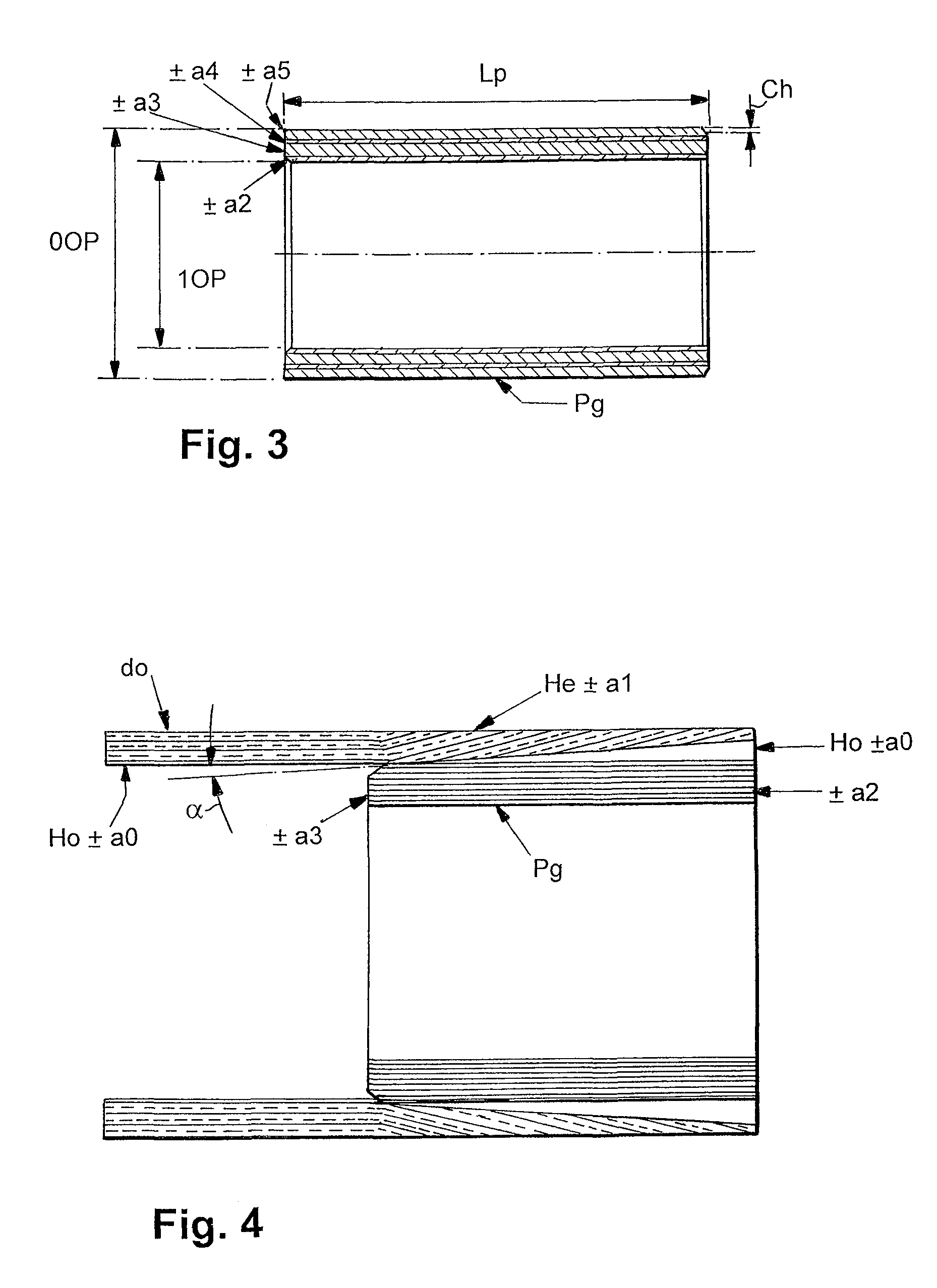
[0018]FIG. 1 shows a composite tube illustrating impregnated fibre layers wound on a former mandrel to form a shaft according to the embodiment of the invention. The main shaft composite construction consisting of a multiplicity of layers of reinforcement at distinct winding angles (±a1, ±ao) to form the main shaft wall. The fibre reinforcement in each layer may be of the same type or may vary between the layers to allow a wider range of tailorable properties of the composite tube to be achieved. FIG. 1 illustrates a two angle, construction, however, any number of layers and winding angles may be used in practice such that the required mechanical properties of the main shaft with inside diameter (di), outside diameter (do) and total composite wall thickness (tc) is built up. The thin inner layer (Ho) is wound at +ao to the axis C / L. The angle ao is preferably 85-89.5° so that the fibre of the layer Ho are close to a hoop orientation as are the end regions which are wound at ±ao in a...
PUM
 Abstract
Description
Claims
Application Information
 - R&D
- Intellectual Property
- Life Sciences
- Materials
- Tech Scout
- Unparalleled Data Quality
- Higher Quality Content
- 60% Fewer Hallucinations
Browse by: Latest US Patents, China's latest patents, Technical Efficacy Thesaurus, Application Domain, Technology Topic, Popular Technical Reports.
© 2025 PatSnap. All rights reserved.Legal|Privacy policy|Modern Slavery Act Transparency Statement|Sitemap|About US| Contact US: help@patsnap.com


