Small-diameter objective optical system

a small-diameter, optical system technology, applied in the field of objective optical systems, can solve the problems of inability to observe, high degree of invasiveness, and significant damage to small laboratory animals, and achieve the effect of minimalism of invasiveness

Active Publication Date: 2010-06-08
EVIDENT CORP
View PDF3 Cites 7 Cited by
  • Summary
  • Abstract
  • Description
  • Claims
  • Application Information

AI Technical Summary

Benefits of technology

[0009]The present invention has been conceived in light of the circumstances described above, and an object thereof is to provide an objective optical system that can carry out in vivo observation of biological tissue, such as cells and muscle tissue, or various internal organs, such as the heart and liver, and particularly brain tissue, of mammals, including small laboratory animals, over a comparatively long period of time with minimal invasiveness.

Problems solved by technology

However, making a large incision is highly invasive to the organism, and therefore, it is not possible to carry out observation for a long period of time.
Furthermore, with the objective optical system in Japanese Unexamined Patent Application, Publication No. 2006-119300, although the tip diameter is small, the degree of invasiveness is still high when observing a site deep inside the brain etc. of a mouse.
However, because the size of the objective lens to be disposed close to the observation site is large compared with the small laboratory animal or the observation target, when observing an internal organ etc. it is necessary to make a large incision in the skin or muscle tissue or to make a large hole.
In such a case, although it is possible to carry out observation directly after making the incision or after drilling the hole, significant damage will be caused to the small laboratory animal.
Therefore, it is difficult to carry out time-lapse observation over a long period of time.
One approach that has been considered is to suture the specimen after observation and to make another incision at the next observation; however, if damage is caused to the small laboratory animal, it is difficult to perform observation under normal conditions over time, which poses a problem.

Method used


Image

  • Small-diameter objective optical system
  • Small-diameter objective optical system
  • Small-diameter objective optical system

Examples


example 1

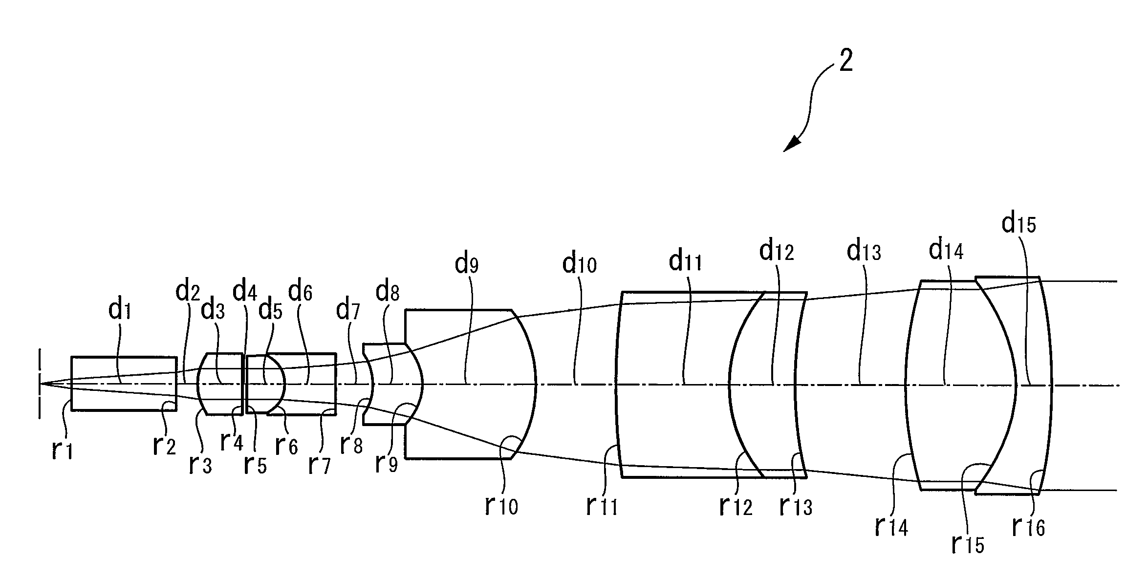
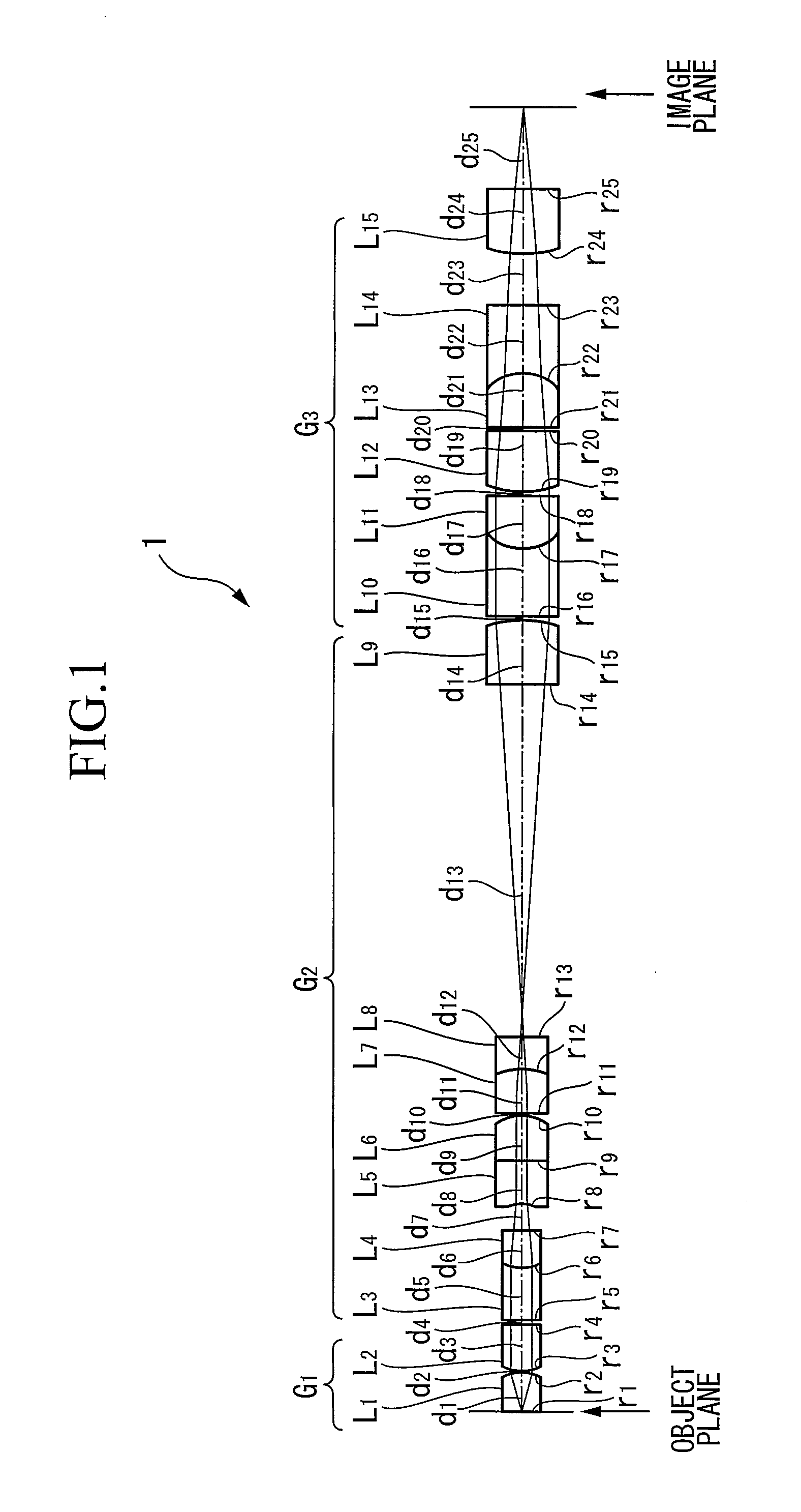
[0072]Example 1 of the present invention will now be described using the small-diameter objective optical system shown in FIG. 1. Table 3 is the lens data for the small-diameter objective optical system in FIG. 1. FIGS. 5A to 5D are aberration curves for the small-diameter objective optical system in FIG. 1. In FIGS. 5A to 5D, reference symbol NA indicates the numerical aperture at the object plane, and reference symbol Y indicates the object height.

[0073]

TABLE 3rdndνdOBJECT PLANE∞0.021.3330455.79(working distance)(water) 1∞0.441.88340.76 2−0.40170.01 3  0.53460.551.88340.76 4∞0.03 5∞0.611.4874970.23 6  0.47860.441.88340.76 7∞0.3 8−0.49330.51.75552.32 9∞0.511.4874970.2310−0.55910.0211∞0.531.75552.3212−0.90210.361.4874970.2313∞4.0914∞0.751.4874970.2315−1.42120.0316∞0.781.88340.7617  0.56250.631.75552.3218∞0.0319  1.00760.711.4874970.2320∞0.0321∞0.631.75552.3222−0.55980.781.88340.7623∞0.5924  1.42670.751.4874970.2325∞0.92

[0074]The lens diameters of L1 to L4 are 0.46 mm, the lens diame...

example 2

[0076]FIG. 6 is a lens diagram of Example 2 of the small-diameter objective lens according to the present invention. The small-diameter objective lens 10 according to Example 2 has a longer working distance WD than that of Example 1. Accordingly, it is possible to perform observation without contacting the tip of the lens with the observation target, so as not to physically affect the living organism.

[0077]Table 4 shows the lens data for the small-diameter objective optical system in FIG. 6. FIGS. 7A to 7D show aberration curves for the small-diameter objective optical system in FIG. 6. The reference symbols in FIGS. 6, 7A to 7D and Table 4 are the same as those in Example 1.

[0078]

TABLE 4rdndνdOBJECT PLANE∞0.051.3330455.79(working distance)(water) 1∞0.41.88340.76 2−0.38210.01 30.5340.61.88340.76 4∞0.04 5∞0.611.4874970.23 60.9980.61.88340.76 7∞0.1 8−0.47610.511.4874970.23 9∞0.51.75552.3210−1.19930.02110.70120.511.4874970.2312∞0.51.75552.3213−0.72570.0514−0.47610.451.88340.7615∞2.5161...


PUM


Abstract

Reducing the outer diameter and effectively correcting various aberrations realizes a small-diameter objective optical system suitable for in vivo observation with a high numerical aperture. The invention provides a small-diameter objective optical system comprising, in order from an object plane a first lens group with positive refractive power, including at least one plano-convex lens whose convex surface faces an image plane; a second lens group with positive refractive power, including at least one concave lens; and a third lens group including a cemented lens of which a cemented surface has negative refractive power. The focal length of the third lens group is larger than the focal length of the first lens group.

Description

BACKGROUND OF THE INVENTION[0001]1. Field of the Invention[0002]The present invention relates to objective optical systems used in applications such as investigating and imaging of cellular function, and more particularly relates to a small-diameter objective optical system suitable for in vivo examination of animals such as mammals.[0003]This application is based on Japanese Patent Application No. 2007-216110, the content of which is incorporated herein by reference.[0004]2. Description of Related Art[0005]At present, a method for observing the behavior of molecules in biological cells and tissue labelled with a dye or fluorescent marker with a fluorescence microscope, a confocal laser-scanning microscope or the like is used.[0006]The behavior of molecules in a living mammalian organism, such as a mouse, sometimes differs from that in culture, and therefore, observation of biological tissue and cells is carried out while the specimen is alive (in vivo). (For example, see Japanese U...

Claims


Application Information

Patent Timeline
Patent Type & Authority Patents(United States)
IPC IPC(8): G02B9/12
CPCG02B23/243G02B21/02
Inventor FUJIWARA, MASATO
Owner EVIDENT CORP
Why Eureka
Try Eureka