
Hip implant

a technology of hip implants and implants, applied in the field of hip implants, can solve the problems of increasing problems, affecting the quality of life of patients, and affecting the quality of life of patients, and besides being of limited effectiveness, can damage the surrounding soft tissue, and be difficult to achieve the effect of preventing recurrence and healing, and reducing the risk of recurrence and recurren

Active Publication Date: 2015-09-10
MJP INNOVATIONS INC
View PDF9 Cites 3 Cited by
  • Summary
  • Abstract
  • Description
  • Claims
  • Application Information

AI Technical Summary

Benefits of technology

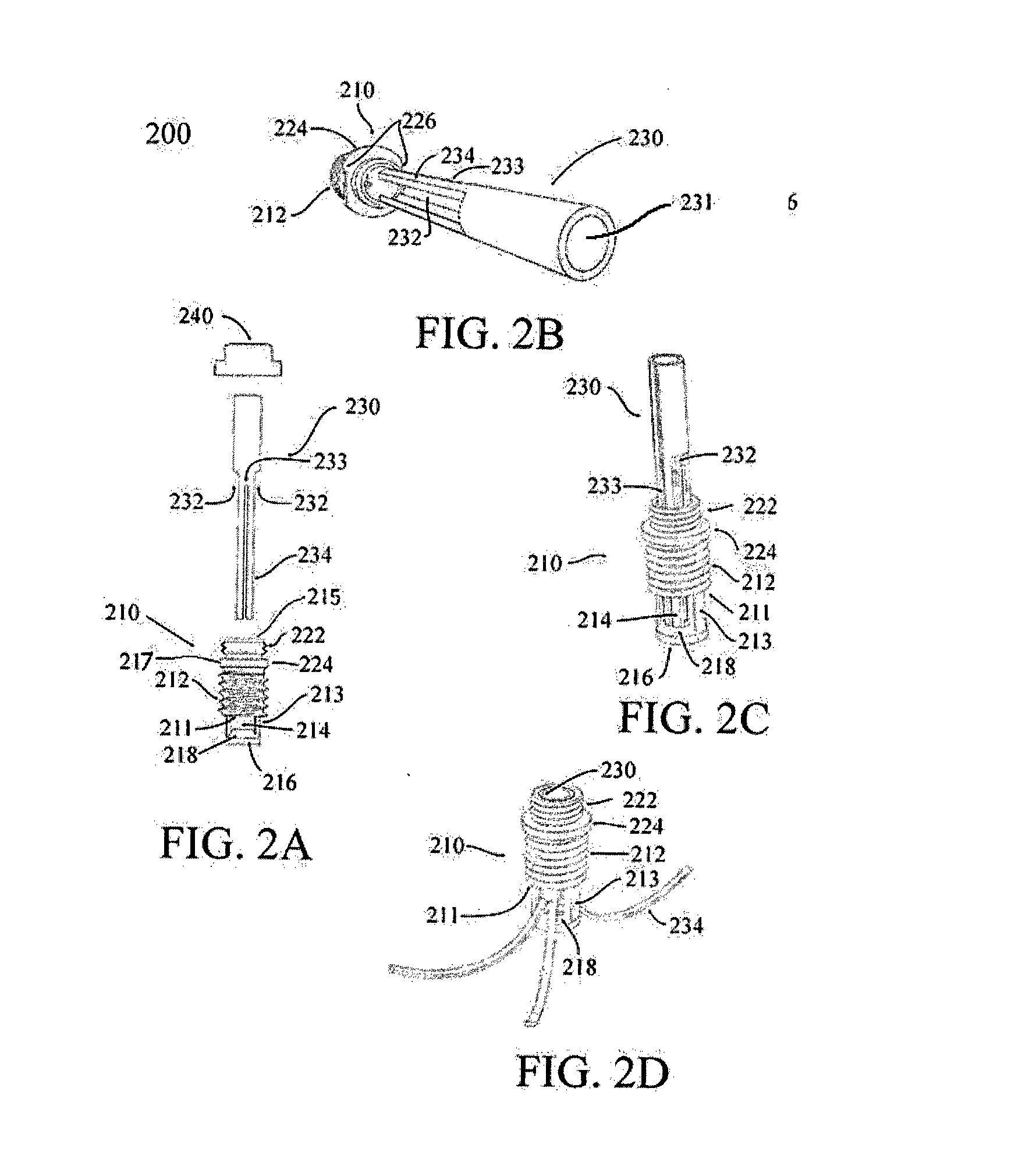
This patent describes a system for treating osteoporotic bones, particularly the femoral neck, using an implant and applicator for screwing and expanding the implant. The implant has an insert body and an expansion tube with cut-outs and slits to define legs that expand radially through windows in the insert body when the expansion tube is pushed against the sloped distal portion of the insert body. An anti-rotation device prevents the expansion tube from rotating within the insert body. The applicator and implant are designed to prevent cold welding during the implantation process. The invention also aims to provide a means for minimal invasiveness during the implant introduction, enhance the stability of a bone implant by guiding healthy cortical bone to less functional trabecular bone areas, and provide accurate and simple positioning of a hip implant.

Problems solved by technology

It is, however, increasingly becoming a problem also for young female athletes (see, e.g., Female Athlete Triad, Switzerland.
One way to prophylactically treat osteoporosis is through the use of pharmaceuticals, which, besides being of limited effectiveness, are often hampered by serious side effects.
This, however, may damage the surrounding soft tissue.

Method used


Image

  • Hip implant
  • Hip implant
  • Hip implant

Examples


Embodiment Construction

[0033]The following description is not intended to limit the scope of the invention in any way as they are exemplary in nature, serving to describe the best mode of the invention known to the inventors as of the filing date hereof. Consequently, changes may be made in the arrangement and / or function of any of the elements described in the exemplary embodiments disclosed herein without departing from the spirit and scope of the invention.

[0034]In the following, a complete system of hip implants and its use will be described. The system comprises the implant itself, and additional devices or “applicators” used for precise positioning of the implant.

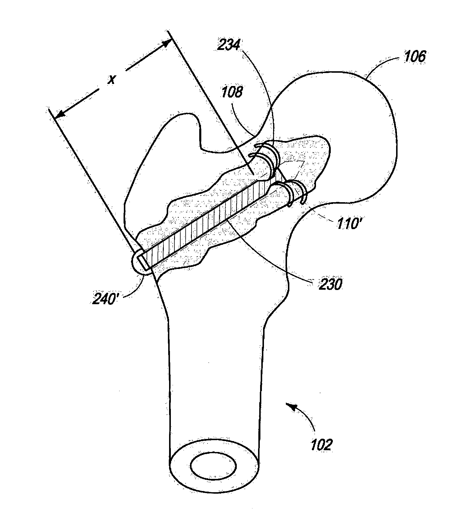
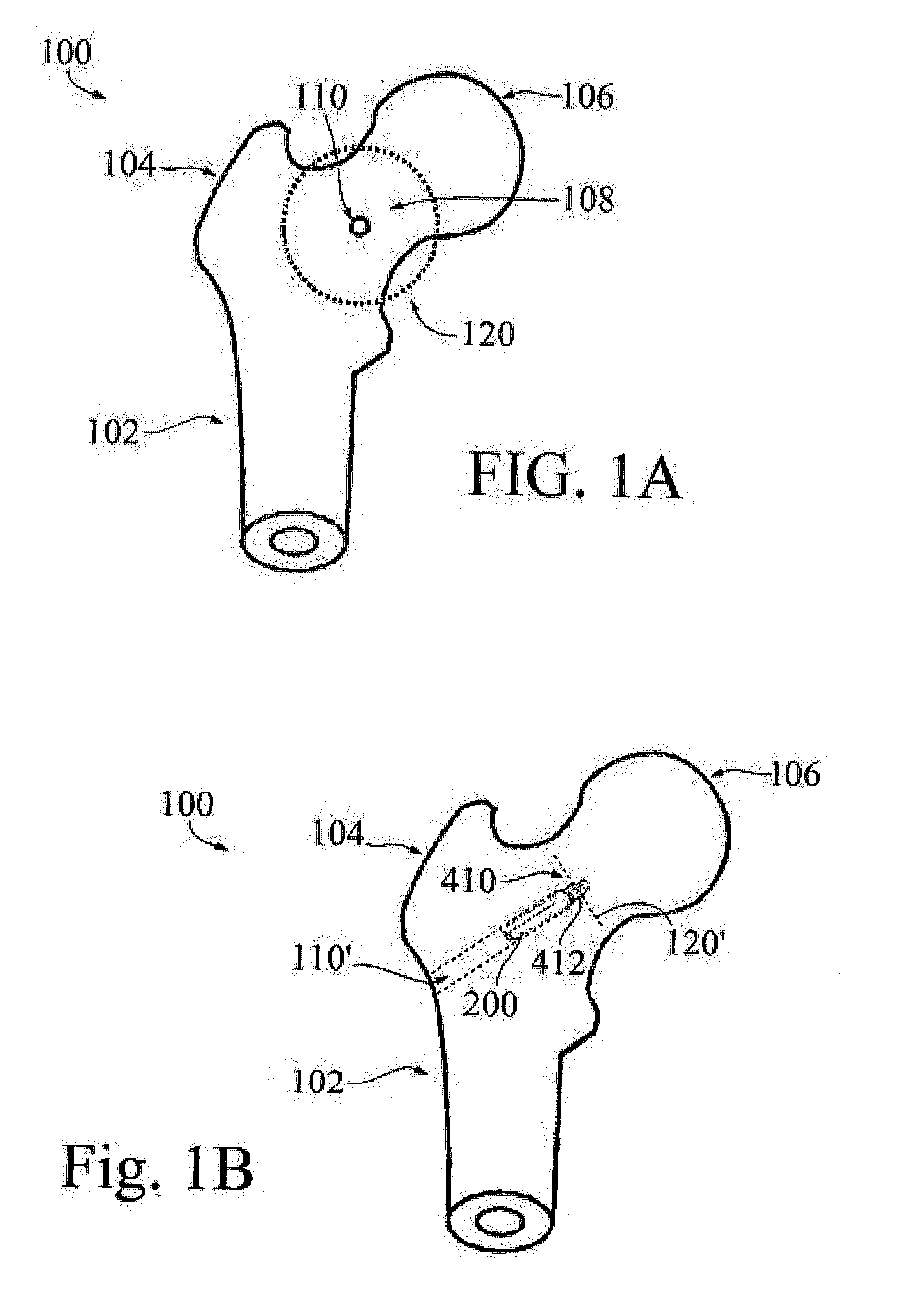
[0035]Referring now to FIG. 1A, part of a femur 100 is shown, with femur body 102, greater trochanter 104, femur head 106 and femur neck 108. The bore 110 for a hip implant is drilled through the cortical bone over Ward's triangle region of the femur neck, in a direction perpendicular to the plane containing femur body 102, femur neck 108 a...


PUM


Abstract

A system and method for forming a hip implant offering minimal invasiveness is described. The system comprises means for positioning the implant under optical and X-ray control, an implant and an applicator for screwing and expanding the implant. The implant includes an insert body and an expansion tube with cut-outs and slits defining legs. The legs expand radially through windows in the insert body when the expansion tube is pushed against the sloped distal portion of the insert body. The expansion process may be ensured by using an anti-rotation device to prevent the insertion tube from rotating within the insert body. Applicator and implant are provided with means preventing cold welding during the implantation process.

Description

CROSS REFERENCE TO RELATED APPLICATIONS[0001]The present application claims the benefit of prior filed U.S. Provisional Patent Application, Ser. No. 61 / 703,327 filed 20 Sep. 2012, which prior application is incorporated herein by reference.COPYRIGHT & LEGAL NOTICE[0002]A portion of the disclosure of this patent document contains material which is subject to copyright protection. The Applicant has no objection to the facsimile reproduction by anyone of the patent document or the patent disclosure as it appears in the Patent and Trademark Office patent file or records, but otherwise reserves all copyright rights whatsoever. Further, no references to third party patents or articles made herein is to be construed as an admission that the present invention is not entitled to antedate such material by virtue of prior invention.FIELD OF THE INVENTION[0003]This invention relates to a system, devices and methods for bone reinforcement, especially for the treatment of osteoporosis.BACKGROUND ...

Claims


Application Information

Patent Timeline
Patent Type & Authority Applications(United States)
IPC IPC(8): A61B17/72A61B17/88
CPCA61B17/8872A61B17/725A61B17/8883A61B17/1742A61B17/7266A61B17/742A61B17/844A61B17/8615A61B17/862A61B17/8625A61B17/864A61B17/8685A61B17/8891A61B2017/561A61B2017/8655A61B17/888F04C2270/041
Inventor PHILIPPON, MARC JOSEPH
Owner MJP INNOVATIONS INC
Learn More