Method and system for dynamically adjusting packet size to decrease delays of streaming data transmissions on noisy transmission lines

a technology of noisy transmission lines and dynamic adjustment, applied in data switching networks, instruments, frequency-division multiplexes, etc., to achieve the effect of reducing the delay of streaming data transmission

Inactive Publication Date: 2010-06-08
INT BUSINESS MASCH CORP
View PDF13 Cites 13 Cited by
  • Summary
  • Abstract
  • Description
  • Claims
  • Application Information

AI Technical Summary

Benefits of technology

[0005]adjusting a packet size by the data transmission server, the packet size being a size associated with each packet of the plurality of packets, the adjusting the packet size including utilizing the first measurement and facilitating a reduction of the delay,
[0008]Advantageously, the present invention provides a technique for dynamically adjusting packet size to decrease a delay of a streaming data transmission on a noisy transmission line.

Problems solved by technology

wherein the delay results from noise on one or more communication link segments over which the streaming data transmission is sent from the data transmission server to the client computing unit.

Method used


Image

  • Method and system for dynamically adjusting packet size to decrease delays of streaming data transmissions on noisy transmission lines
  • Method and system for dynamically adjusting packet size to decrease delays of streaming data transmissions on noisy transmission lines
  • Method and system for dynamically adjusting packet size to decrease delays of streaming data transmissions on noisy transmission lines

Examples


first embodiment

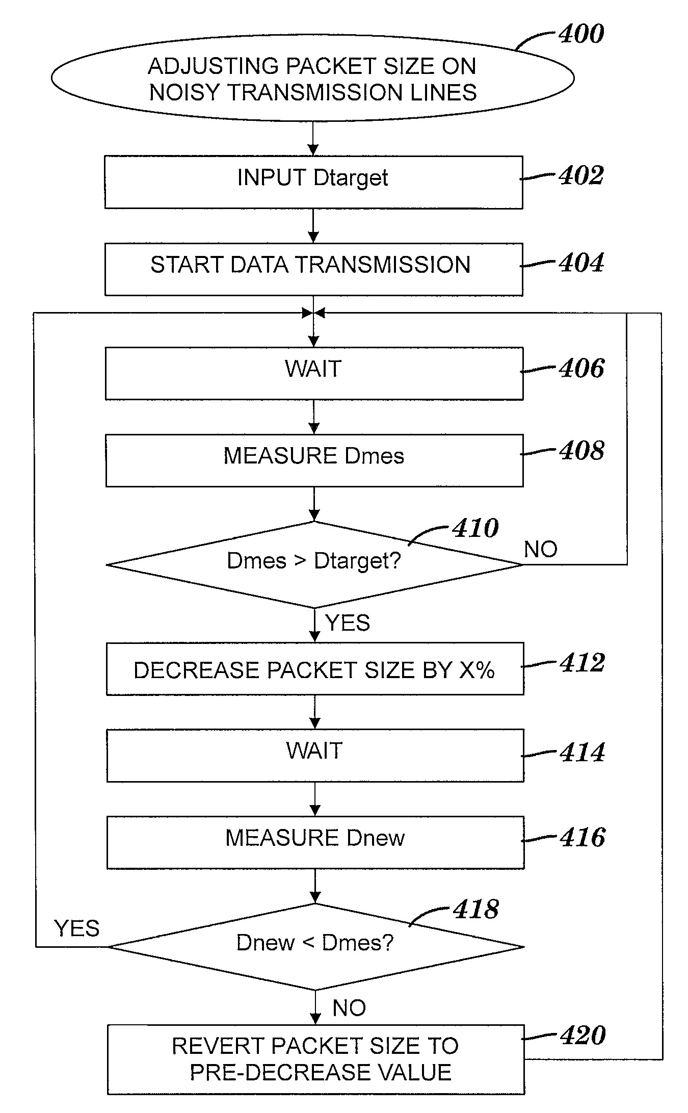
[0033]In the first embodiment described above relative to step 408, data transmission server 302 (see FIG. 3) separates the data stream transmission into TCP packets and sends them to cell phone 306 (see FIG. 3). In response to server 302 (see FIG. 3) sending a packet of the data stream transmission, a timestamp is added to a timestamp table. An entry in the timestamp table identifies a portion of data in the data stream and the time that the portion of data was sent (e.g., an entry in the form ). Cell phone 306 (see FIG. 3) confirms the reception of the selected portion by sending a message (a.k.a. confirmation message) to data transmission server 302 (see FIG. 3) that reports the bytes that make up the selected portion. Data transmission server 302 (see FIG. 3) examines the data stream and identifies the location of the selected portion within the data stream. In the timestamp table, data transmission server 302 (see FIG. 3) looks up the timestamp associated with the identified lo...

second embodiment

[0034]In the second embodiment described above relative to step 408, cell phone 306 (see FIG. 3) receives the data stream transmission, assembling the transmission from incoming TCP packets over a primary connection. Data transmission server 302 (see FIG. 3) sends the selected portion of the data stream transmission out of band in a separate pacing connection (e.g., by a TCP connection separate from the primary connection). Cell phone 306 (see FIG. 3) receives the selected portion in the out of band data and determines a first timestamp indicating the receipt time of the selected portion in the out of band data. As cell phone 306 (see FIG. 3) continues to receive the data stream transmission via the primary connection, the cell phone attempts to match the selected portion with a portion of the incoming data stream. When cell phone 306 (see FIG. 3) finds a match for the selected portion, the cell phone determines a second timestamp of the time that the match was found. Cell phone 306...


PUM


Abstract

A method and system for dynamically adjusting packet size to decrease a delay of a streaming data transmission. A measurement is obtained by a measuring computing unit (i.e., data transmission server or client computing unit). The first measurement is either (1) a delay of a streaming data transmission being sent from the data transmission server to the client computing unit via a plurality of packets or (2) a frequency of damaged packets of the plurality of packets. The damaged packets contribute to the delay of the streaming data transmission. The packet size is adjusted by the data transmission server. The packet size adjusting includes utilizing the measurement and facilitating a reduction of the streaming data transmission delay. The delay results from noise on one or more communication link segments used by the streaming data transmission.

Description

FIELD OF THE INVENTION[0001]The present invention relates to method and system for dynamically adjusting packet size to decrease delays of a streaming data transmission.BACKGROUND OF THE INVENTION[0002]In conventional Transmission Control Protocol / Internet Protocol (TCP / IP)-based communication of continuous data streams (e.g., video streams) where the data receiver is separated from the data transmitter by one or more link segments on which data can be damaged (i.e., distorted), the overall communication line throughput suffers due to the fact that the longer a TCP packet is, the more likely the data is distorted. In certain data receivers such as cell phones receiving video streams, when a TCP packet for a continuous data stream is distorted (i.e., any number of bits are missing or the bits indicate an incorrect value), the entire TCP packet is dropped and a retransmission is requested. That retransmission, in turn, is also not guaranteed to be free of distortion, so subsequent ret...

Claims


Application Information

Patent Timeline
Patent Type & Authority Patents(United States)
IPC IPC(8): G01R31/08H04J3/16H04J3/24
CPCH04L65/80H04L69/40H04L65/752
Inventor ANDREEV, DMITRYGRUNIN, GALINAVILSHANSKY, GREGORY
Owner INT BUSINESS MASCH CORP
Why Eureka
Try Eureka