Shock absorber

a technology of shock absorber and side buffer, which is applied in the direction of railway bodies, transportation and packaging, window arrangements, etc., can solve the problems of the side buffer's absorbance, the damping element integrated in the side buffer is usually unable to absorb the total resulting energy, and the ship's hull being damaged

Inactive Publication Date: 2010-06-15
VOITH PATENT GMBH
View PDF19 Cites 13 Cited by
  • Summary
  • Abstract
  • Description
  • Claims
  • Application Information

AI Technical Summary

Benefits of technology

[0023]It is to be noted at this point that the invention is not only to be considered as providing additional shock absorbance for use with a side buffer. Rather, the shock absorber is suited in general for any end face of a supporting structure which serves to transfer the forces occurring during normal vehicle operation, such as for example, the end or contact surface of a wharfage, a buffer stop or a structural element for a vehicle. The structural element for a vehicle can in particular also be a crossbeam running for example in front of the front end of the car body, which is for example, configured—as described in printed publication DE 10 126 483 A1—as a bumper bar and fixed to the front end of a rail vehicle by means of side energy-absorbing elements and a base frame. This bumper bar can be arranged in the horizontal coupling plane, for example, and thereby serves to protect the front end of the car body from damage resulting from impacts.
[0047]Thus, in this embodiment, the shock absorber is used in combination with a buffer device, normally used for example as a side buffer. This buffer device thereby serves as a regeneratively-designed shock absorber, in which the impact forces occurring for example between the individual car bodies of a multi-member vehicle during the normal operation of a vehicle are absorbed or damped. However, upon the operative load of the regeneratively-designed damping element (regeneratively-designed energy-absorbing element) integrated in the buffer device being exceeded, the shock absorber downstream the buffer device is activated, wherein the impact energy is converted into the work of deformation and heat by a defined plastic deformation of the deformation tube provided in the shock absorber. Thus, the regeneratively-configured damping element (spring device) as well as the other components of the shock absorber can be effectively protected against destruction or damage in the event of a crash.

Problems solved by technology

When the elastic damping capacity of fenders employed as such is exceeded, however, the risk arises of the ship's hull being damaged since when a ship for example strikes undamped against a wharf, the resultant impact energy acts undampened on the ship's hull.
The damping of impact forces and the effective absorbing of impact energy resulting from an impact is a general problem, particularly with moving objects, when due to the mass of the object, high kinetic energies which are to be absorbed in a defined manner pursuant a predictable sequence of events need to be factored in.
While the impact forces which occur during normal operation of the vehicle, for example between individual car bodies of a multi-member vehicle, are absorbed by the regeneratively-designed damping element integrated in the side buffer, when the operating load of the side buffer is exceeded, however, for instance when the vehicle collides with an obstacle or when the vehicle is abruptly braked, the damping element integrated in the side buffer is usually unable to absorb the total resulting energy.
The shock absorbance provided by the side buffer is thus, no longer integrated into the energy-absorbing concept of the vehicle as a whole such that the resulting impact forces are transmitted directly to the vehicle undercarriage.
This subjects same to extreme loads with the potential to damage or even destroy same.
This increased contracting length allows the plastic deformation of the buffer housing upon overload so that this solution enables a destructive conversion of impact energy into the work of deformation and heat.
Even if the side buffer known from this art can protect the vehicle undercarriage up to a certain degree from damage upon severe collisions, it is thereby not possible to adapt the additional shock absorber to specific applications.
In particular, the known solution is unsuited for many applications since the maximum energy absorption achievable with the deformation of the buffer housing is often too low.
A further disadvantage can be seen in the fact that after the additional shock absorber has been activated, the entire side buffer needs to be replaced since the shock absorber is integrated into the side buffer and because due to the deformation of the buffer housing, the side buffer can no longer be used in normal vehicle operation.
The problem described above not only applies to shock absorbers designed in the form of a bumper; i.e., as a structural element mounted to the front end of a rail vehicle.

Method used


Image

  • Shock absorber
  • Shock absorber
  • Shock absorber

Examples


first embodiment

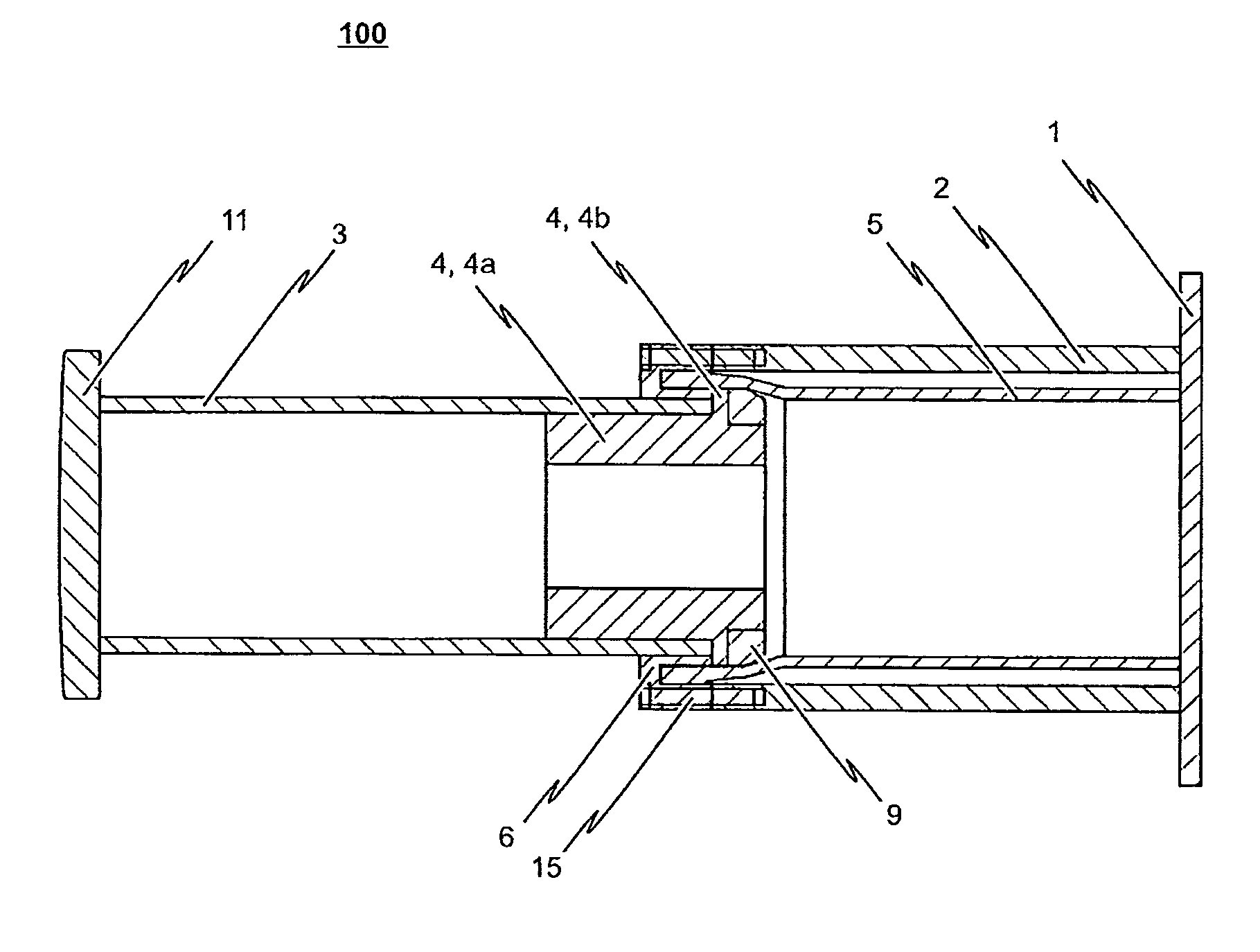
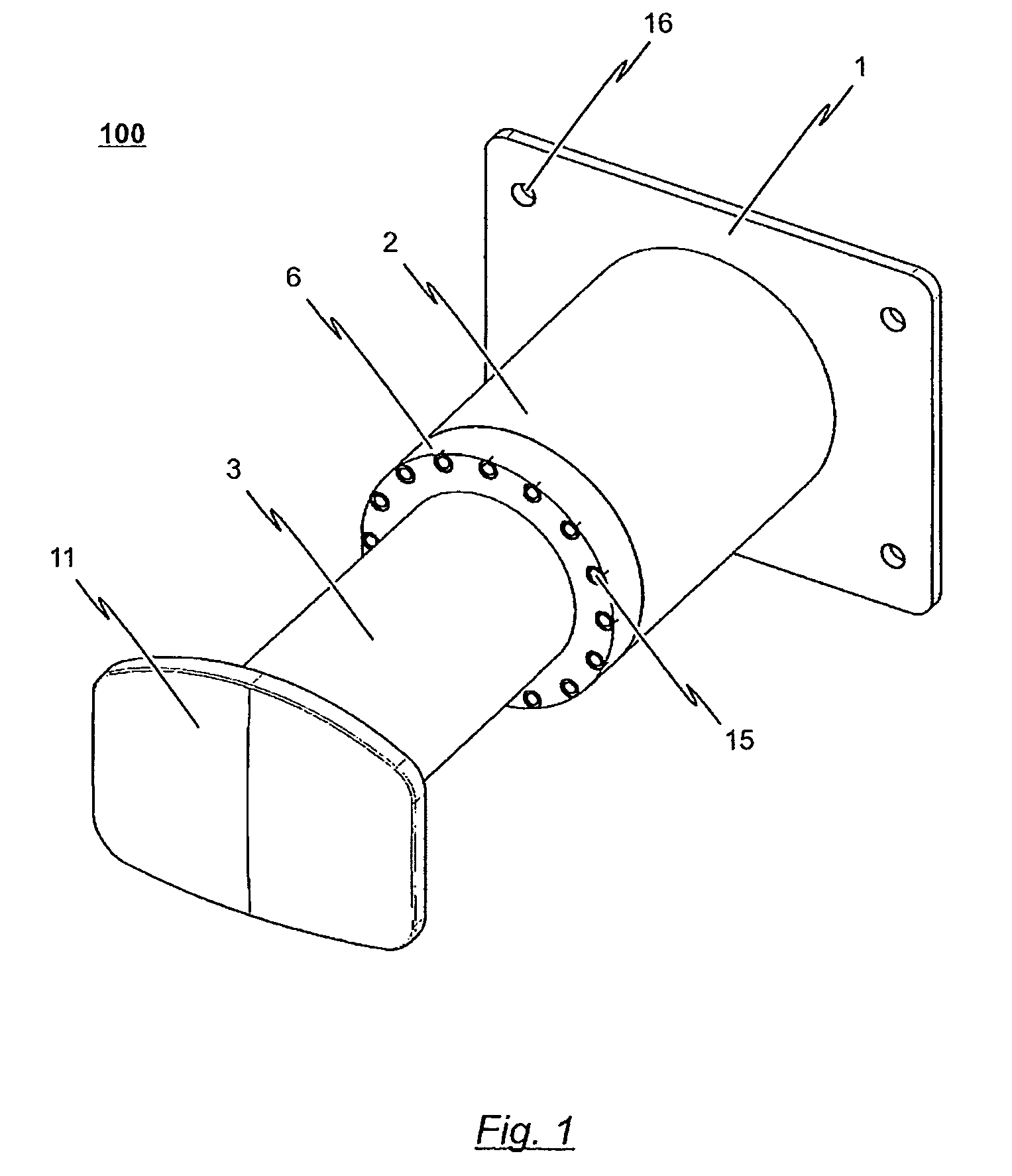
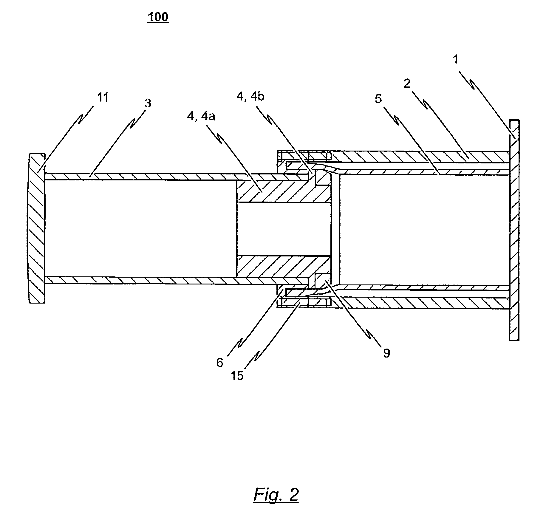
[0075]The shock absorber 100 in accordance with the first preferred embodiment is suitable as an irreversible shock-absorbing stage which, additionally to any given damping elements (such as e.g., side buffers) or energy-absorbing units there may be, can be mounted as one complete exchangeable modular unit to a support frame or the undercarriage of, for example, a railcar body. To this end, the shock absorber 100 in accordance with the first embodiment comprises a base plate 1 configured as a flange which can be mounted for example with bolts to the (not explicitly shown) supporting structure. Throughholes 16 are thereby preferably provided in base plate 1 through which the bolts used to fix the shock absorber 100 can be guided.

[0076]The shock absorber 100 according to the first embodiment includes a support frame 2 which is fixedly connected to the base plate 1. In detail, the support frame 2 of the embodiment depicted is configured as a tube section of circular cross-section. A de...

second embodiment

[0092]the inventive shock absorber 100 provides a complete exchangeable module which can be mounted for example to a supporting structure for a railcar body. This is thus, a shock absorber which, due to the integration of the buffer device 12, also exhibits effective damping properties during normal vehicle operation. The buffer device integrated in shock absorber 100 can for example, serve as a regeneratively-designed shock absorber, in which the impact forces occurring for example between the individual car bodies of a multi-member vehicle during normal operation of the vehicle can be absorbed or damped. When the operating load of the regeneratively-designed damping element 14 of buffer device 12 integrated in shock absorber 100 is exceeded, however, the energy-absorbing unit (deformation tube 5) of the shock absorber 100 downstream the buffer device 12 is activated, whereby the impact energy is converted into the work of deformation and heat by a defined plastic deformation of sa...

third embodiment

[0095]To this end, the shock absorber 100 includes a base plate 1, by which the shock absorber 100 can be detachably affixed to the supporting structure. Conceivable hereto would be for example providing throughholes 16 in base plate 1 to receive screws, pins, bolts, etc. ultimately serving to fix the base plate 1 to the supporting structure.

[0096]Instead of throughholes 16, however, other solutions would also be conceivable as fixing means or mechanism. For example, if due to structural design contingencies, base plate 1 can only be provided with a relatively small edge area in which there would not be enough space for the appropriate throughholes 16, respectively insufficient space for screws, bolts, etc. to be received in the throughholes 16, it would be suitable to weld or otherwise affix a nipple or the like to the rear side of base plate 1; i.e. the side of base plate 1 faced away from the support frame 2, wherein only this nipple serves to fix the shock absorber 100 to the s...


PUM


Abstract

The invention relates to a shock absorber (100), in particular for use as an additional irreversible shock-absorbing stage together with a component for transferring force. In order to achieve the reliable dissipating of high impact energies, a shock absorber (100) comprising the following is indicated in accordance with the invention: a base plate (1); a force-transferring element (3) having a tensioning element (4); an energy-absorbing element in the form of a deformation tube (5) which is connected by a first end section to the base plate (1); and a connecting element (6) for the disengageable connecting of the force-transferring element (3) to a second end section of the deformation tube (5), wherein the connecting element (6) is pressed against the tensioning element (4) such that the deformation tube (5) is braced between the tensioning element (4) and the base plate (1) without play.

Description

CROSS-REFERENCE TO RELATED APPLICATIONS[0001]The present invention claims priority from European Patent Application No. 07 116 138.4, filed Sep. 11, 2007, the contents of which are herein incorporated by reference in their entirety.BACKGROUND OF THE INVENTION[0002]1. Field of the Invention[0003]The present invention relates to a shock absorber, including for use as an additional irreversible shock-absorbing stage together with a component for transferring force.[0004]2. Description of the Related Art[0005]To protect the outer hull of a ship against damage when maneuvering in a port or when anchoring at a wharf, it is known to make use of so-called fenders. Normally, a fender acting as a protective body is thereby positioned between the ship and the wharf such that it serves as a shock absorber on the one hand and, on the other, as a spacer so that the hull is not chafed. Independently devised fenders are usually used for larger ships, these being a component of the wharfage facility...

Claims


Application Information

Patent Timeline
Patent Type & Authority Patents(United States)
IPC IPC(8): B61D15/06
CPCB61G7/10E02B3/26B61G11/16Y02A30/30
Inventor GANSWEIDT, MICHAEL
Owner VOITH PATENT GMBH
Why Eureka
Try Eureka