Arrangement and method for adjustment of rail at a conveyor

a technology of adjustment method and conveyor, which is applied in the direction of conveyor control device, conveyor parts, conveyors, etc., can solve the problems of time-consuming adjustment process, complicated adjustment of different guide rail mounts on curved conveyors, and production stoppages, and achieves high degree of precision and easy fitting

Active Publication Date: 2010-06-15
FLEXLINK COMPONENTS
View PDF14 Cites 17 Cited by
  • Summary
  • Abstract
  • Description
  • Claims
  • Application Information

AI Technical Summary

Benefits of technology

[0009]An object of the invention is to provide an arrangement for guide rail adjustment on a conveyor which solves the aforementioned problems with previously known arrangements for guide rail adjustments. A further object of the invention is to provide an arrangement for guide rail adjustment on a conveyor which is easy to fit and which provides for a simultaneous adjustment of the position of number of guide rails with a high degree of precision.
[0011]The rotational motion of the synchronous motors is translated into a linear motion of the moveably supported guide rails, making it possible to ensure that the guide rails are moved an equal distance.
[0017]Both of these embodiments rely on the fact that a synchronous motor increases the torque delivered until the motor can no longer turn. When the motor is no longer able to turn the motor stops without sustaining any damage. The fact that all motors are brought to a standstill when the guide rails are driven against a common reference stop therefore means that the adjustment of the guide rails is calibrated throughout the entire set of mounting elements. When the motors are then driven in the opposite direction, the guide rails retain their calibration and the movement varies only as a function of how long the motors are run. The operating time is the same for all the motors, so that the positions of all guide rails accurately remain the same.
[0018]The fact that a synchronous motor stops when it is overloaded can also be used to provide an arrangement for adjusting the position of a set of guide rails, in which the risk of injury to persons or damage to objects due to jamming is reduced. By selecting a synchronous motor and a transmission between synchronous motor and guide rail which ensures that the synchronous motor stops at a suitably low jamming force, a safe and functional arrangement is obtained.

Problems solved by technology

There is a great risk, especially in cases where, for design reasons, the base surface of the bottles is designed with a small diameter in relation to the height of the bottle, that the bottle will tip over, resulting in production stoppages.
One problem with manual adjustment is that the adjustment process is time-consuming.
One of the disadvantages of this type of arrangement is that adjustment of different guide rail mounts is complicated on curved conveyors.
Where cardan shafts are used, as have been proposed in U.S. Pat. No. 5,211,280 and U.S. Pat. No. 5,291,988, there is a risk of too much play between the various parts of the shafts, so that the adjustment becomes different for different guide rail mounts on the same conveyor.
An input angle of rotation of 360° naturally always corresponds to an output angle of rotation of 360°, but within the revolution variations will occur unless very special and therefore expensive cardan joints are used.
Where a flexible shaft is used, as has been proposed in WO 00 / 17073, there is a risk that the shaft will also be torsionally flexible, with the result that the adjustment will become different for different guide rail mounts on one and the same conveyor.
Where the flexibility is instead achieved by joining together a number of rigid elements, the same problem as with cardan shafts will occur, with the risk of too much play between the elements or the fact that the reproduction of the angle is not identical over the joint connecting the parts together.
This means that the oil-air mixture will become compressible, with the result that stable adjustment of fixed guide rail positions is rendered impossible.
This is a disadvantage where the arrangement is to be used in the food industry, where the leakage of hydraulic oils is undesirable.
The solution proposed in the document EP 1331182 presents the problem that the control cable can become locked, with the result that the adjustment becomes different for different guide rail mounts on one and the same conveyor.
In addition, there are relatively tight restrictions with regard to the maximum radius of curvature of a control cable of the Bowden type.
Should the cable be bent too much, the risk of the cable locking is dramatically increased.
This means that the cables must hang relatively freely, with the result that they take up a lot of space.
This also increases the risk of somebody or something getting caught in the cables, with the risk of a cable breaking.

Method used


Image

  • Arrangement and method for adjustment of rail at a conveyor
  • Arrangement and method for adjustment of rail at a conveyor
  • Arrangement and method for adjustment of rail at a conveyor

Examples


Embodiment Construction

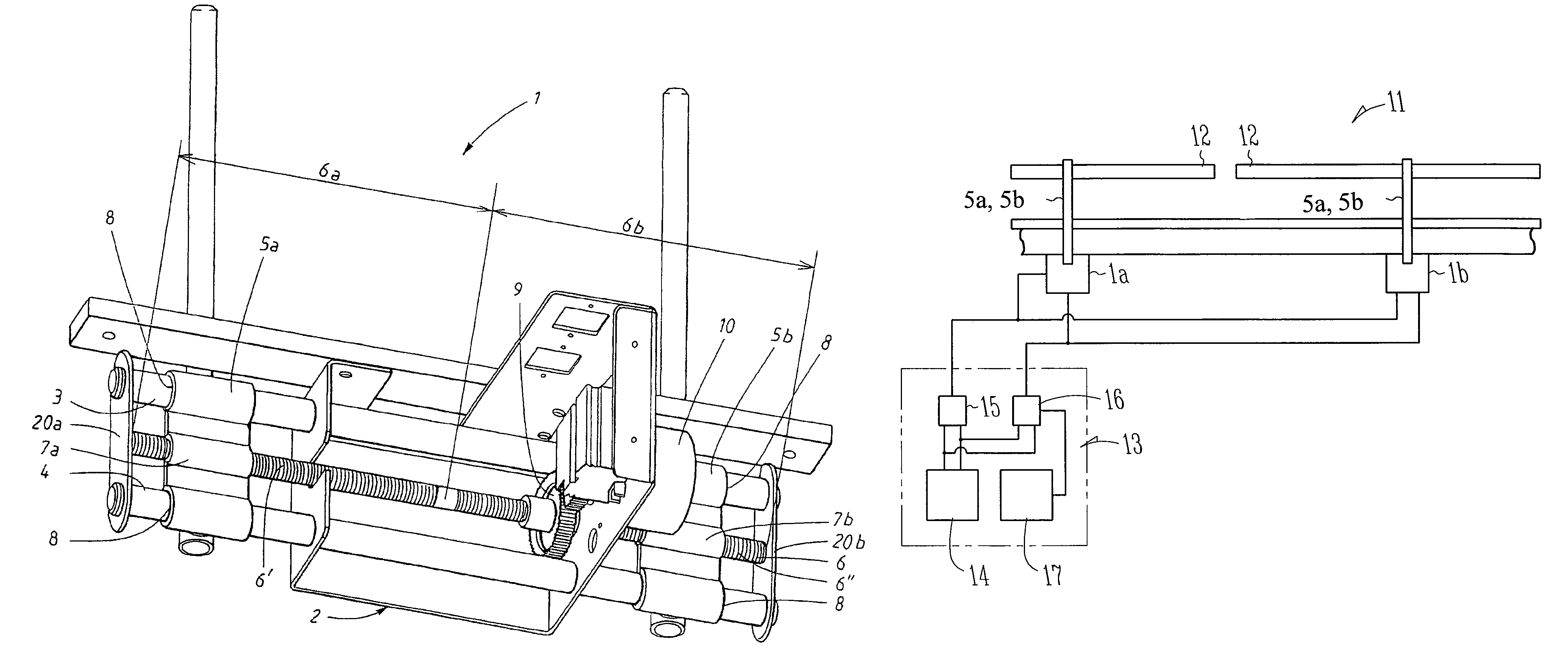
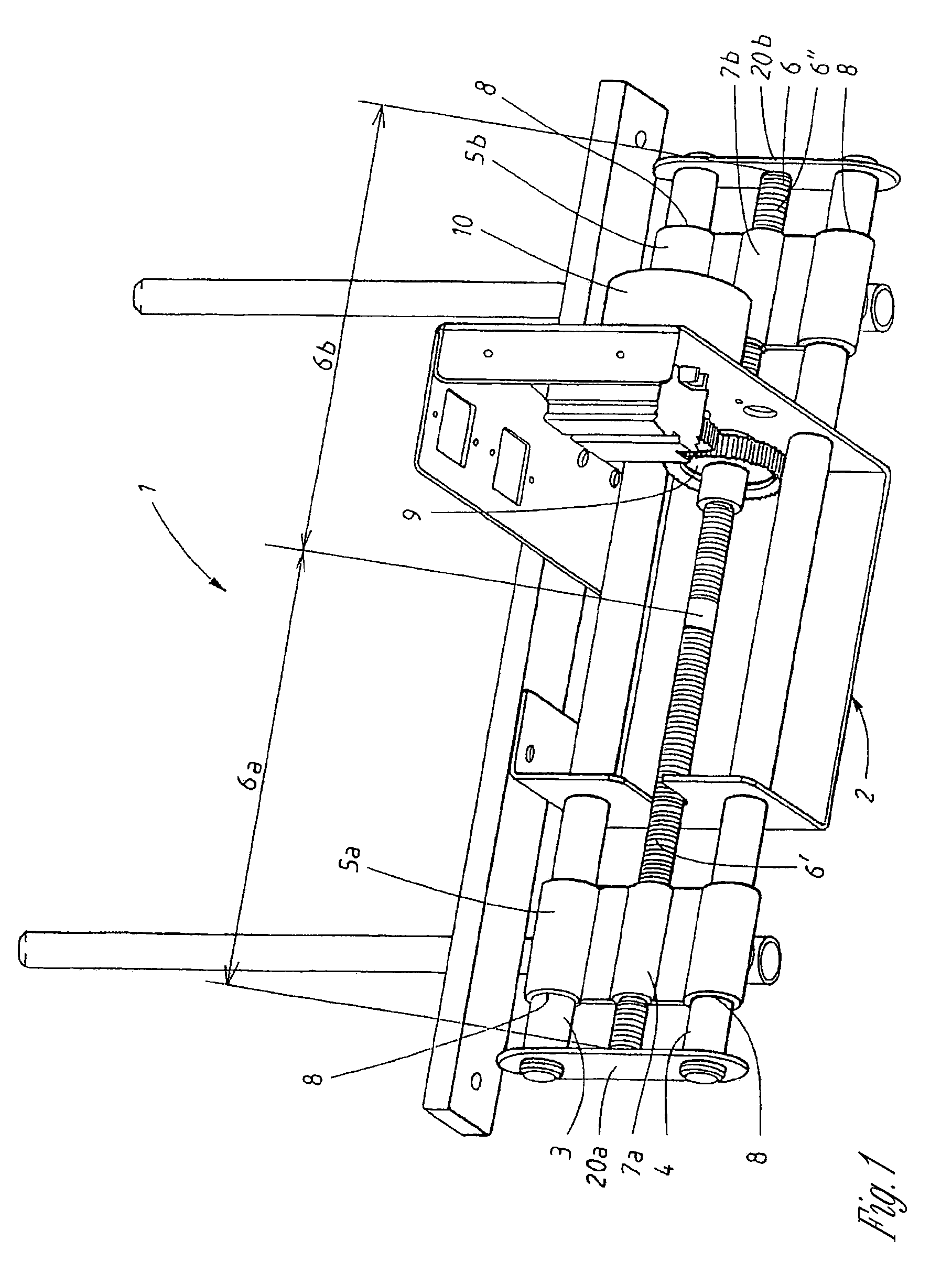
[0024]FIG. 1 shows a mounting element 1, which is designed to support two moveably suspended guide rails. The mounting element 1 comprises a housing 2, in which slide rails 3, 4 are arranged in order to support a first and a second guide rail mount 5a, 5b. A threaded rod 6 is also rotatably supported in the mounting element. The rod 6 has an external thread with a screw thread 6′ on one half 6a of the rod and an opposite-handed screw thread 6″ on its other half 6b. The guide rail mounts 5a, 5b both have an internally threaded cylinder 7a, 7b, the cylinders being designed to engage with the threaded rod 6. The guide rail mounts furthermore have recesses 8 designed, through interaction with the slide rails 3, 4, to support the guide rail mounts 5a, 5b. The guide rail mounts 5a, 5b also have a support to which the guide rail (not shown) is subsequently fixed.

[0025]A gear wheel 9 is fixed on the rod 6. The gear wheel is driven by a synchronous motor 10. The gear wheel 9 may be driven di...


PUM


Abstract

An arrangement and a method for guide rail adjustment on a conveyor, the arrangement comprising a set of guide rails, a set of mounting elements, which each support at least one moveably suspended guide rail, and means for simultaneous individual adjustment of said set of mounting elements, the means permitting simultaneous adjustment of the position of the guide rails moveably supported by the mounting elements.

Description

RELATED APPLICATIONS[0001]This application is a nationalization under 35 U.S.C. 371 of PCT / SE2005 / 000784, filed May 26, 2005 and published as WO 2005 / 118437 A1 on Dec. 15, 2005, which claimed priority under U.S.C. 119 to Swedish Application No. 0401426-2, filed Jun. 1, 2004, which applications and publication are incorporated herein by reference and made a part hereof.FIELD OF THE INVENTION[0002]The present invention relates to an arrangement for guide rail adjustment on a conveyor according to the preamble of claim 1, and to a method for guide rail adjustment on a conveyor according to the preamble of claim 8. It relates in particular to an arrangement which will facilitate adjustment of the position of a guide rail arranged on a conveyor. The invention may be used in adjusting the height of a guide rail and in adjusting the lateral position of a guide rail in relation to the conveyor.DESCRIPTION OF THE PRIOR ART[0003]When conveying articles in general, and particularly when convey...

Claims


Application Information

Patent Timeline
Patent Type & Authority Patents(United States)
IPC IPC(8): B65G21/20B65G15/00B65G17/00B65G
CPCB65G21/2072B65G21/20
Inventor LUNDBERG, HAKON
Owner FLEXLINK COMPONENTS
Why Eureka
Try Eureka