
Area light source and lightguide used therefore

a technology of light source and lightguide, which is applied in the direction of lighting and heating equipment, instruments, mechanical equipment, etc., can solve the problems of insufficient prevention of luminance reduction, non-uniformity of luminance distribution, and luminance lowering

Inactive Publication Date: 2010-06-15
MITSUBISHI CHEM CORP
View PDF21 Cites 40 Cited by
  • Summary
  • Abstract
  • Description
  • Claims
  • Application Information

AI Technical Summary

Benefits of technology

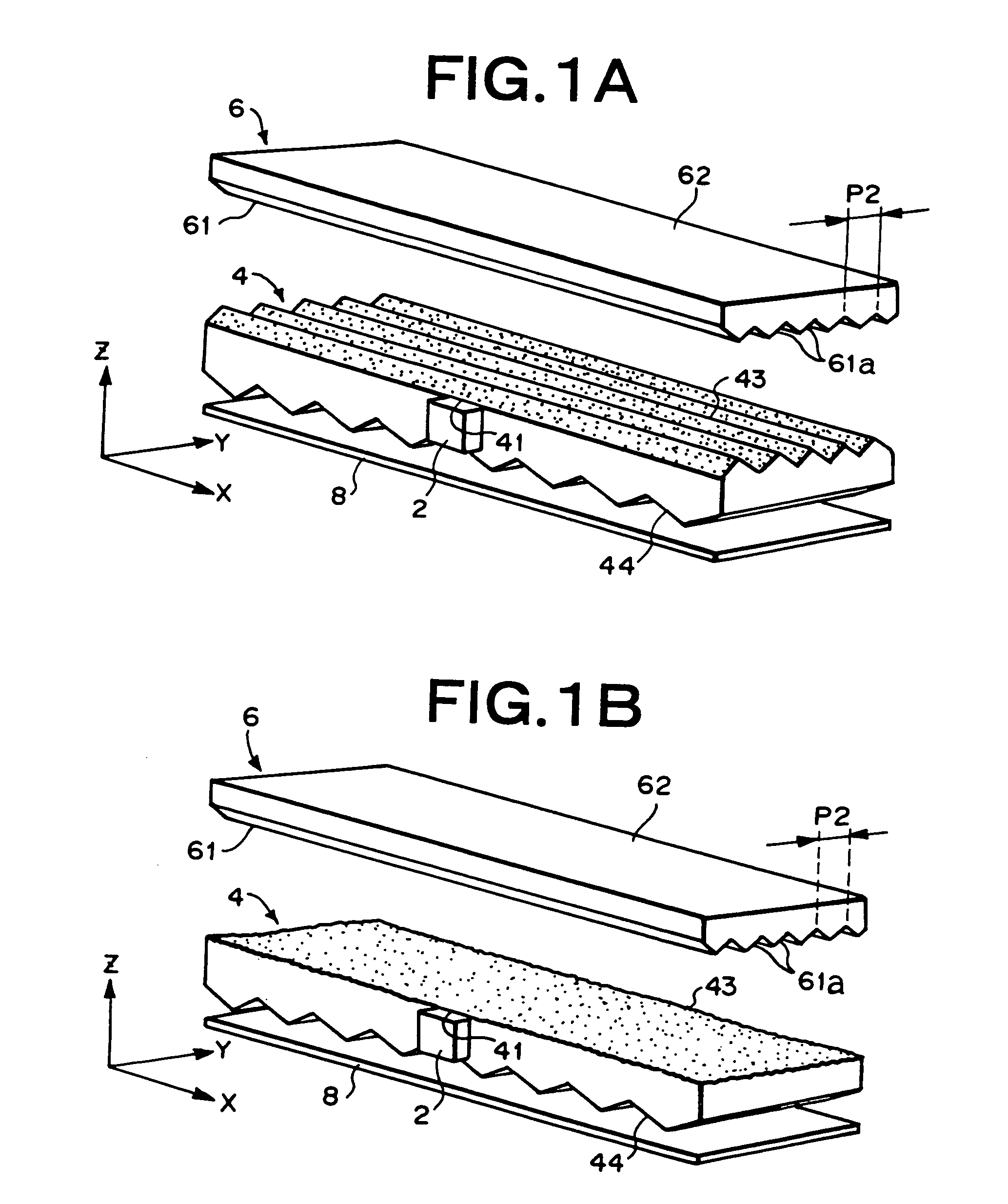
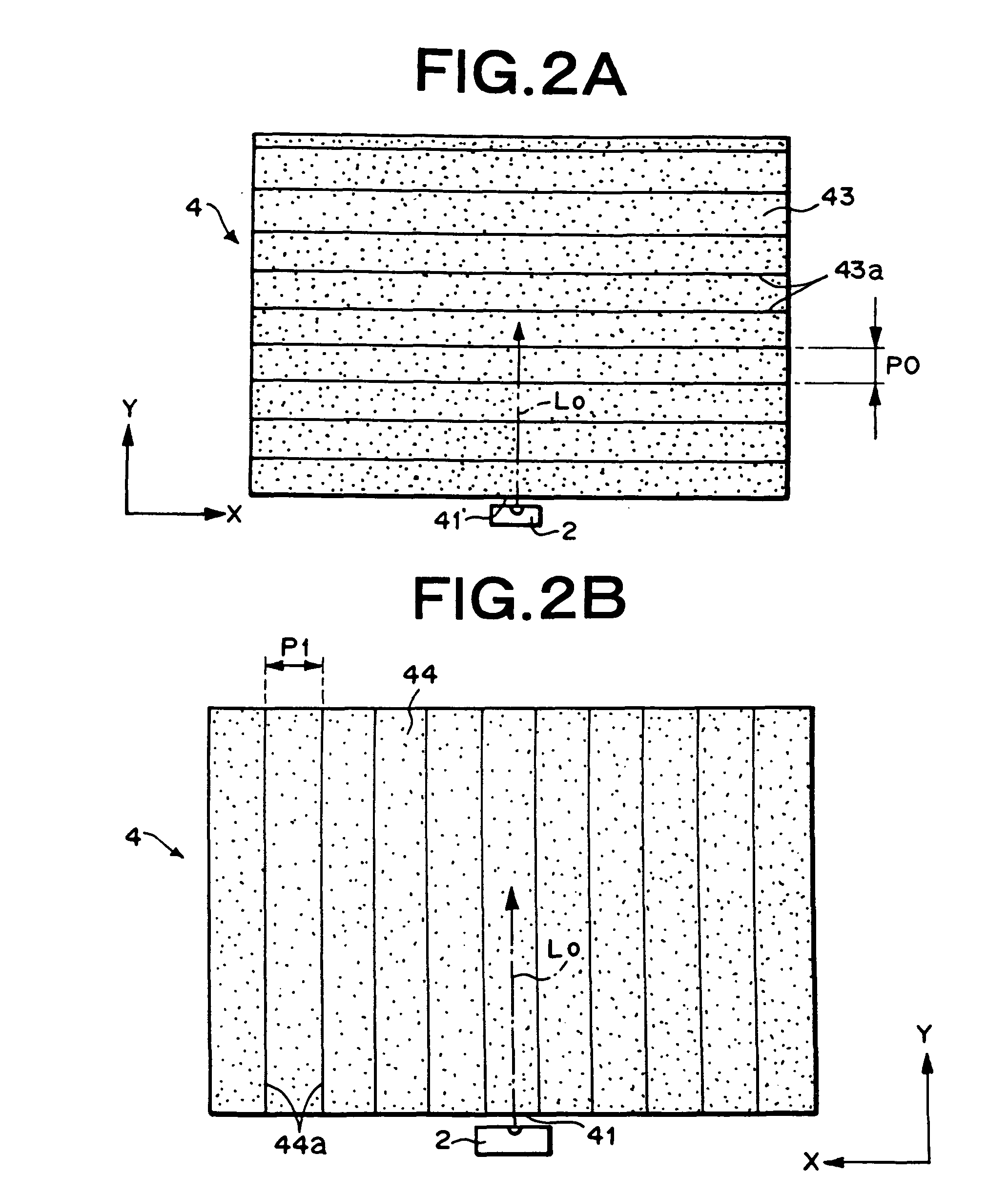
[0170]As described above, according to the present invention, the plurality of elongated lenses are formed on one of the light emitting face of the light guide and the back surface thereof, and the rough surfaces are disposed on at least a part of the surfaces of the elongated lenses and / or at least a part of the surface on the opposite side to the surface on which the elongated lenses are formed. Thus, it is possible to provide a high-quality planer light source device by preventing, without deteriorating an emitted light distribution, lowering of luminance and non-uniformity in luminance distribution brought about by the use of a small number of primary light sources in a point state to achieve low power consumption of the planar light source device.

Problems solved by technology

However, a reduction in the number of LED's brings about lowering of luminance and non-uniformity of a luminance distribution.
In the case of applying such a light emitting structure to the planar light source device that uses the point light source, the device in which the rough surface is formed as the light emitting structure can emit a highly directive light of a narrower emitted light distribution in a plane (perpendicular direction) perpendicular to both of the light incident end face and the light emitting face of the light guide, but cannot sufficiently prevent a reduction of luminance because of a very wide emitted light distribution in a plane (parallel direction) parallel to the light incident end face of the light guide and perpendicular to the light emitting face.
On the other hand, the device in which the lens surface is formed as the light emitting structure can emit a highly directive light of a narrower emitted light distribution in both of parallel and perpendicular directions to achieve high luminance, but has a problem of an extremely narrow distribution range of an emitted light, i.e., several to several tens of degrees, in a plane parallel to the light emitting face.
This condition has a problem of bringing about non-uniformity (i.e., non-uniformity of uniformity degree of luminance) of a luminance distribution in an observation direction on a light emitting surface of the planar light source device.

Method used


Image

  • Area light source and lightguide used therefore
  • Area light source and lightguide used therefore
  • Area light source and lightguide used therefore

Examples


example 1

[0125]An elongated prism pattern in which elongated prisms having isosceles triangular sections of apex angles 172° and pitches of 50 μm were continuously disposed in parallel with a side of a length 34 mm was formed by cutting on a mirror-finished surface of a brass plate of an effective area 34 mm×48 mm and a thickness 3 mm. Then, the surface was roughened by using glass beads (FGB-400 by Fuji Manufacturing Co., Ltd.) of particle diameters of 53 μm or less, and subjecting the entire surface to blasting at a distance of 40 cm from the brass plate to a spray nozzle, and at spray pressure of 0.4 kgf / cm2. Thus, a first mold having a shape transfer surface of the roughened elongated prism pattern was obtained.

[0126]Additionally, a second mold made of a mirror-finished brass plate having an effective area of 34 mm×48 mm and a thickness of 3 mm was obtained.

[0127]Injection molding of a transparent methacrylic resin was carried out by using the first and second molds to manufacture a tran...

example 2

[0131]An elongated prism pattern in which elongated prisms having isosceles triangular sections of apex angles 1300 and pitches of 50 μm were continuously disposed in parallel with a side of a length 48 mm was formed by cutting on a mirror-finished surface of a brass plate of an effective area 34 mm×48 mm and a thickness 3 mm. Thus, a second T-old having a shape transfer surface of the elongated prism pattern was obtained.

[0132]By using the first mold used in the Example 1 and the above second mold, injection molding was carried out as in the case of the Example 1 to manufacture a transparent acrylic resin plate formed into a rectangle of a short side 34 mm and a long side 48 mm, and into a wedge shape whose thickness was changed from 1 mm to 0.7 mm along the long side, one surface of which had a first elongated prism formed surface having a roughened surface, and the other surface of which had a second elongated prism formed surface. This resin plate was set as a light guide.

[0133]...

example 3

[0135]A circular-arc elongated prism pattern in which circular-arc elongated prisms having isosceles triangular sections of apex angles 160° and pitches of 30 μm were concentrically formed around the vicinity of one corner of a square shape of 48 mm×34 mm, and flat parts of 30 to 200 μm were formed between every adjacent circular-arc elongated prisms so as to gradually narrow its width as the distance from the center increases was formed by cutting in an effective region of 40 mm×30 mm on a mirror-finished surface of a brass plate of 48 mm×34 mm and a thickness 3 mm. Then, the surface was roughened by using glass beads (FGB-400 by Fuji Manufacturing Co., Ltd.) of particle diameters of 53 μm or less, and subjecting the entire surface to blasting at a distance of 40 cm from the brass plate to a spray nozzle, and at spray pressure of 0.2 kgf / cm. Thus, a first mold having a shape transfer surface of the roughened elongated prism pattern was obtained.

[0136]By using the obtained first mol...


PUM


Abstract

A plate-shaped light guide for a planar light source device that guides a light emitted from a primary light source includes a light incident end face, a light emitting face and a back surface on the opposite to the light emitting face, wherein a plurality of first elongated lenses having an average slant angle of 0.5 to 60° are continuously or intermittently formed on one of the light emitting face and the back surface, and at least a portion of a surface of each first elongated lens, or at least a portion of the other one of the light emitting face and the back surface, or at least the portion of the surface of each first elongated lens and at least the portion of the other one of the light emitting face and the back surface includes a rough surface having an average slant angle of 0.1 to 8°.

Description

[0001]This is a Divisional of application Ser. No. 10 / 491,635 filed on Apr. 2, 2004 now abandoned, which is a U.S. National Stage Entry of PCT / JP02 / 10369 filed on Oct. 4, 2002, and claims benefit of Japanese Patent Applications No. 2001-325204 and 2001-309134, filed Oct. 23, 2001 and Oct. 4, 2001, respectively.BACKGROUND OF THE INVENTION[0002]1. Field of the Invention[0003]The present invention relates to a planar light source device of an edge light system, and more particularly to a planar light source device which uses a point light source such as a light emitting diode (LED) designed to realize miniaturization and a reduction in power consumption. The planar light source device of the present invention is suitably applied to a backlight of a relatively compact liquid crystal display device used as a display panel of a portable electronic device such as a cellular phone, or an indicator of various devices.[0004]2. Background of the Related Art[0005]Recently, the liquid crystal di...

Claims


Application Information

Patent Timeline
Patent Type & Authority Patents(United States)
IPC IPC(8): F21V7/04F21V8/00
CPCG02B6/0038G02F1/1335
Inventor YAMASHITA, TOMOYOSHIHAYASHI, YASUKO
Owner MITSUBISHI CHEM CORP
Learn More