Rotor design for submersible electronic generator

a technology of electronic generators and rotors, which is applied in the direction of sea energy generation, non-positive displacement fluid engines, liquid fuel engine components, etc., can solve the problems of seaweed and the potential for fish kill and other marine species injury, and the collection of seaweed and other submerged debris on the rotor

Inactive Publication Date: 2010-06-15
CARR FRED K
View PDF9 Cites 21 Cited by
  • Summary
  • Abstract
  • Description
  • Claims
  • Application Information

AI Technical Summary

Benefits of technology

[0026]A further objective of the invention is to provide a variable pitch rotor blade where the pitch of the blade relative to the flow of water can be adjusted and maintain determining the amount of kinetic energy removed from the flowing water.
[0027]A further objective of the invention is to p...

Problems solved by technology

The wider the rotor sweep path, that is the diameter from rotor tip to rotor tip, the greater the potential for fish kill and other marine species injury.
In addition, the elliptically curved design set at forty five degrees in the rotor path tends to push the fish aside rather...

Method used


Image

  • Rotor design for submersible electronic generator
  • Rotor design for submersible electronic generator
  • Rotor design for submersible electronic generator

Examples


Embodiment Construction

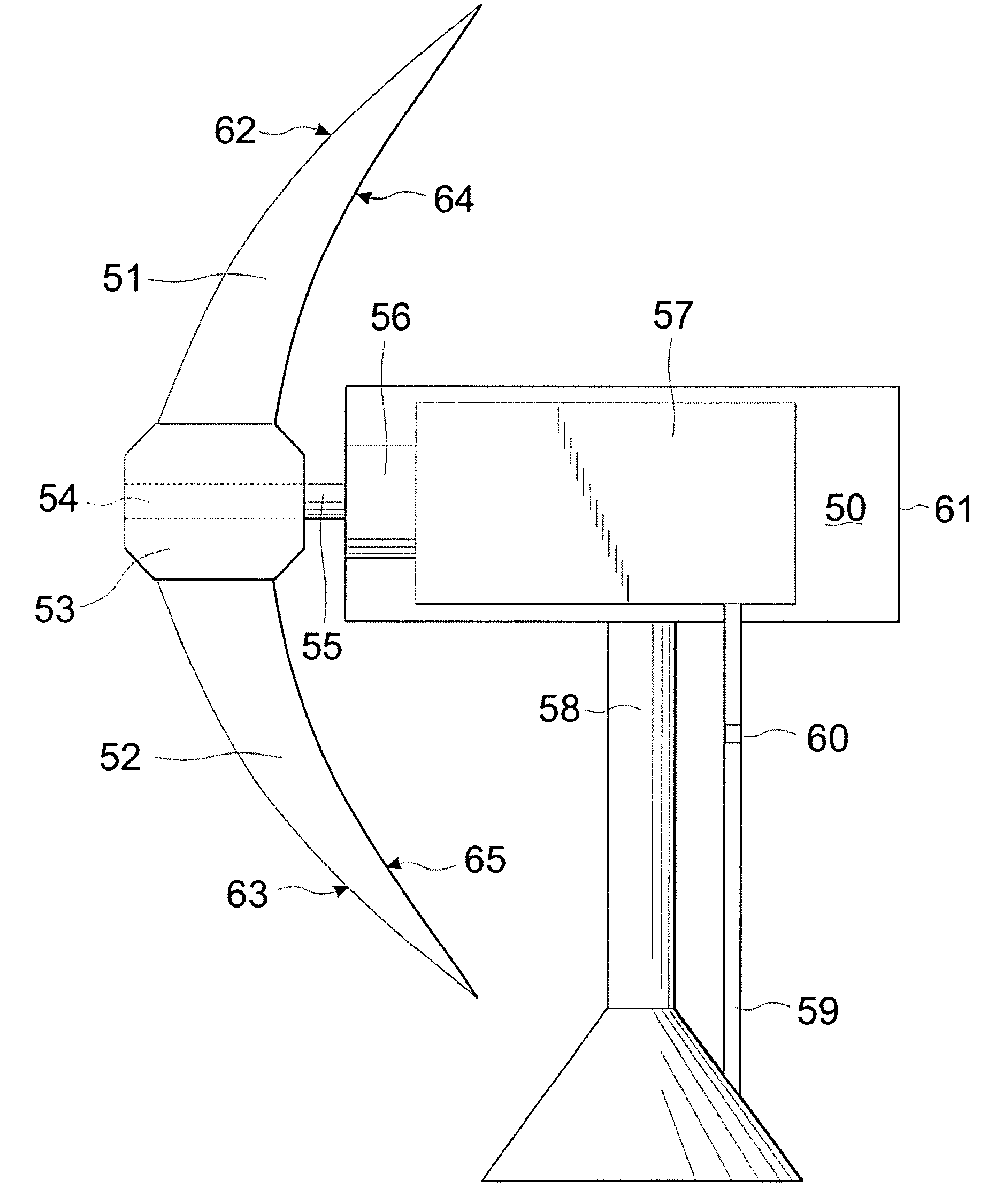
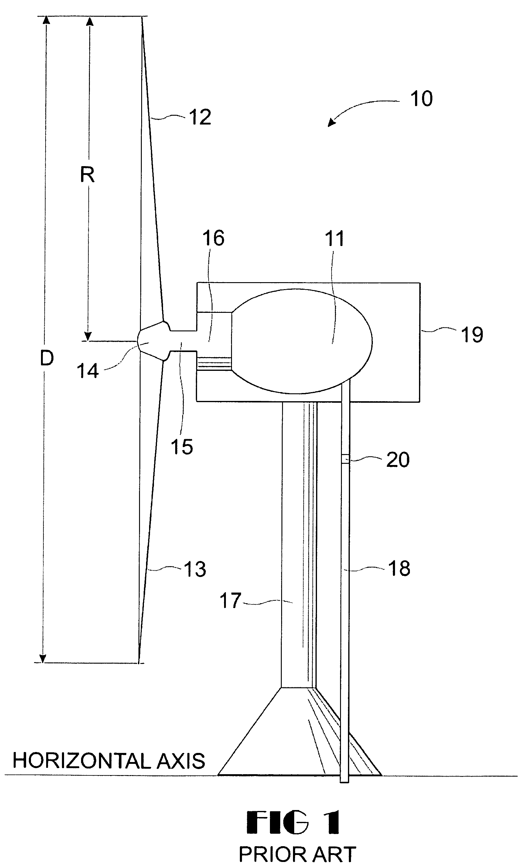
[0043]Referring now to the drawings, and first to FIG. 1, there is shown a schematic view of a typical prior art electrical power current generating system, generally designated 10. The power current generator 10 includes an electrical generator 11, rotor blades 12,13 attached to a rotor hub 14 which is further attached to a rotor shaft15 which is connected to step-up gears 16. The rotor shaft 15 has an external portion exterior to the generator housing 19 connecting to the rotor hub 14 and an interior portion interior in the generator housing 19 connecting to the step-up gear box 16. The rotor shaft 15 transfers the harnessed rotating mechanical energy to the step-up gear box 16 which in turn increases the rotation speed sufficient to generate electricity.

[0044]The kinetic energy in the water current causes the rotor blades 12,13 to rotate which in turn cause the rotor shaft 15 to turn since both are commonly attached to the rotor hub 14. Water is several hundred times denser than ...


PUM


Abstract

An improved rotor blade used in combination with a submersible electrical generator comprises a rotor base with width W, a leading edge, a tip, and a trailing edge. The leading edge and the trailing edge are defined as elliptical curves having a radius of 8.0(W). A straight line drawn from the front of the base to the lip forms a forty five degree angle with respect to the rotor base. The rotor blade is functionally connected to a rotor shaft through a pivotal support axial which allows the pitch of the blade to be set and maintained. The pitch is set to harness the kinetic energy of flowing water thereby generating electricity.

Description

BACKGROUND OF THE INVENTION[0001]1. Field of the Invention[0002]The present invention relates to the generation of electrical power from submerged generators using tidal currents to turn the generators, but it may be adapted to more powerful ocean current applications.[0003]2. Description of the Prior Art[0004]The decrease in the amount and production of world crude oil, and North America natural gas, presents a potential catastrophic problem for the industrial world. While the amount and location of crude oil reserves are not well documented, it is acknowledged that there is limited amount of the fossil fuels in reserve. In addition, many feel that the combustion of the fossil fuels for transportation and energy production contributes to global warming. It would therefore be a worthwhile thing to switch from fossil fuels for energy production to energy sources which are self-sustaining and non-polluting. Other recently investigated possibilities for renewable resources include wind...

Claims


Application Information

Patent Timeline
IPC IPC(8): F03B3/06F03B3/12F03B3/14
CPCF03B3/06F03B13/264F03B17/061Y02E10/28F05B2250/71F05B2260/74Y02E10/223F05B2240/30Y10S416/05Y10S416/02Y02E10/20Y02E10/30
Inventor CARR, FRED K.
Owner CARR FRED K
Why Eureka
Try Eureka