Stepped-reflector antenna for satellite communication payloads

a satellite communication and payload technology, applied in the field of antenna systems, can solve the problems of large peak-to-edge gain variation of the receiver beam, and achieve the effect of improving the performance of one band and reducing peak-to-edge gain variation

Active Publication Date: 2010-06-15
LOCKHEED MARTIN CORP
View PDF20 Cites 161 Cited by
  • Summary
  • Abstract
  • Description
  • Claims
  • Application Information

AI Technical Summary

Benefits of technology

[0006]In accordance with the present invention, a stepped reflector antenna is provided. The reflector has an annular region that is axially stepped a height h above or below the central region. The height h is chosen to create a desired 180° phase reversal at a receive frequency of the refl

Problems solved by technology

Although this type of antenna system is significantly better than conventional MBA systems, the receive

Method used


Image

  • Stepped-reflector antenna for satellite communication payloads
  • Stepped-reflector antenna for satellite communication payloads
  • Stepped-reflector antenna for satellite communication payloads

Examples


Embodiment Construction

[0029]In the following detailed description, numerous specific details are set forth to provide a full understanding of the present invention. It will be apparent, however, to one ordinarily skilled in the art that the present invention may be practiced without some of these specific details. In other instances, well-known structures and techniques have not been shown in detail to avoid unnecessarily obscuring the present invention.

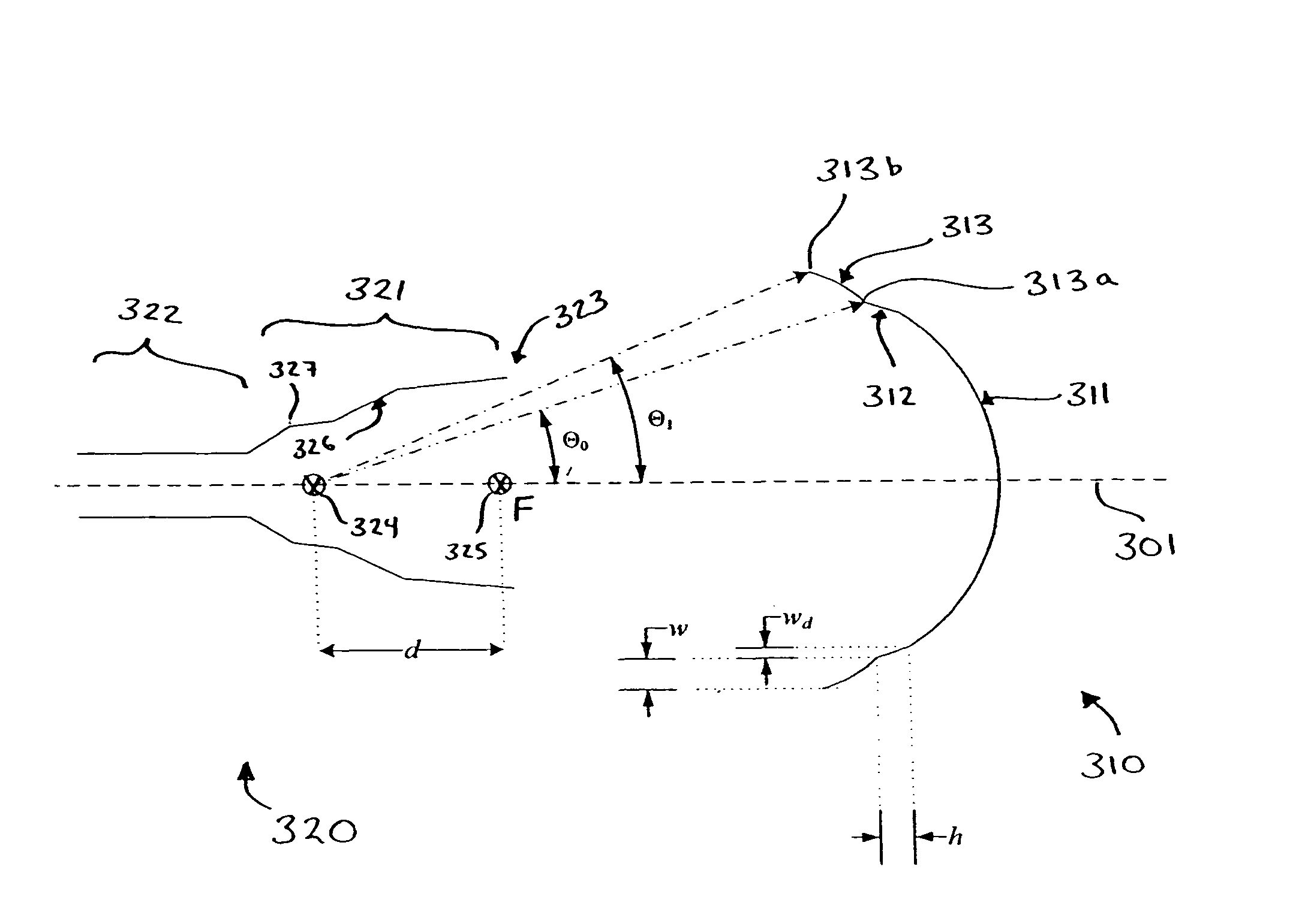
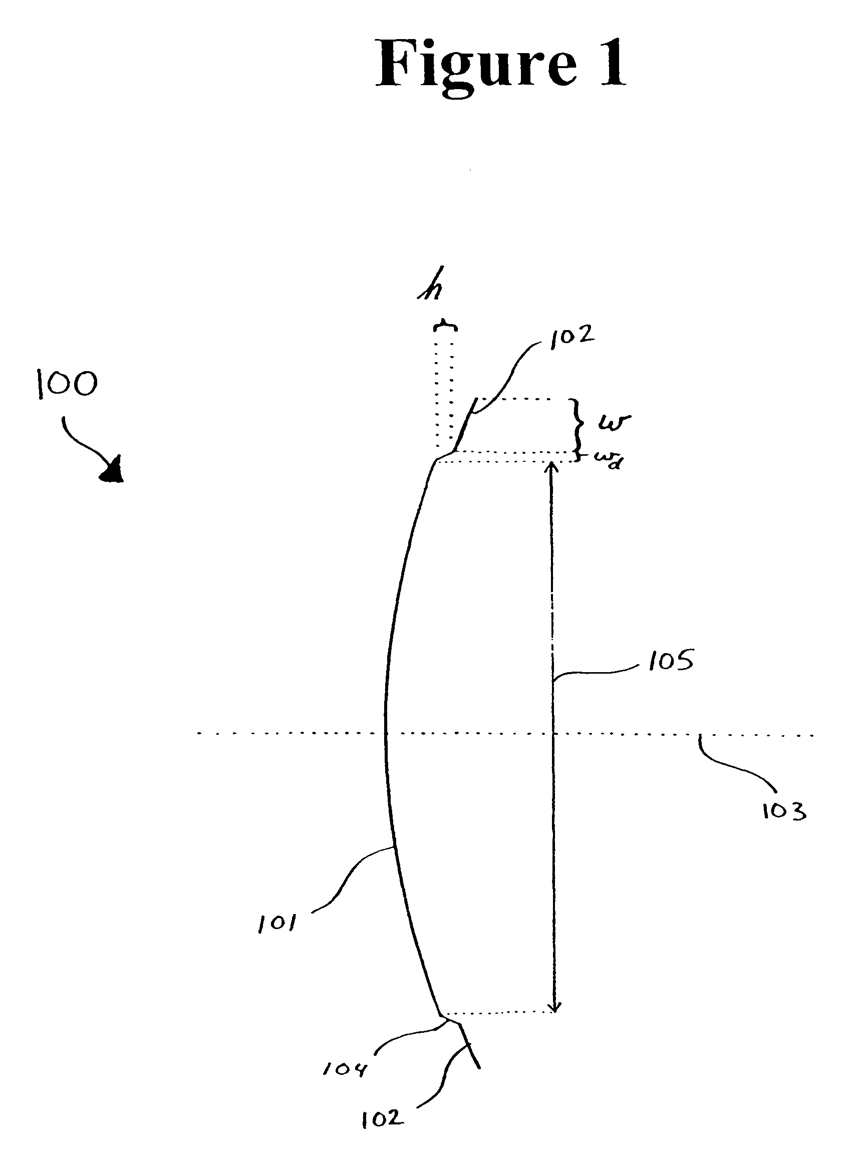
[0030]FIG. 1 illustrates a schematic profile of a stepped reflector according to one embodiment of the present invention. Stepped reflector 100 includes a central region 101 and an annular region 102 surrounding central region 101. Central region 101 has a diameter 105. Annular region 102 has an annular width w, and is axially stepped a height h above central region 101 along axis 103. In the present illustration, the size of height h has been exaggerated for clarity. Between annular region 102 and central region 101, stepped reflector 100 includes a disc...


PUM


Abstract

A stepped reflector for being illuminated by at least one multiple-band feed is provided. The reflector includes a central region and a first annular region with an annular width of w. The first annular region is axially stepped a height h above the central region, where h is approximately equal to
m×[Φ±(ϕ(Θ=0)-ϕ(Θ=Θ0))]×π180×λ2π×12,
where m is a positive odd integer, Φ is a desired amount of phase shift of an outer region of a phase front for reflecting off of the reflector, φ is a feed phase contribution for an angle Θ, and Θ0 is an angle formed between an axis of the at least one feed and a line connecting a phase center of the at least one feed and an inner edge of the at least one annular region.
The central region and the annular region of the reflector may be parabolically curved or may alternately be shaped. The reflector may be fed by one or more multiple-band horn antennas.

Description

CROSS-REFERENCE TO RELATED APPLICATION[0001]The present application claims the benefit of priority under 35 U.S.C. §119 from U.S. Provisional Patent Application Ser. No. 60 / 693,832 entitled “ENHANCED STEPPED-REFLECTOR ANTENNA SYSTEM FOR DUAL-BAND MULTIPLE BEAM SATELLITE PAYLOADS,” filed on Jun. 27, 2005, the disclosure of which is hereby incorporated by reference in its entirety for all purposes.FIELD OF THE INVENTION[0002]The present invention generally relates to antenna systems and, in particular, relates to a stepped reflector antenna (“SRA”) for use in multiple beam antenna systems.BACKGROUND OF THE INVENTION[0003]Dual-band antenna systems, operating simultaneously at both uplink and downlink frequencies of a multiple beam communication satellite, have the advantage of using half the number of reflectors and half the number of feed horns, when compared with a conventional multiple beam antenna (“MBA”) with a separate set of reflector antennas for each uplink and downlink band. ...

Claims


Application Information

Patent Timeline
IPC IPC(8): H01Q13/00H01Q5/55
CPCH01Q13/025H01Q5/55H01Q19/12H01Q15/16
Inventor RAO, SUDHAKAR K.TANG, MINH
Owner LOCKHEED MARTIN CORP
Why Eureka
Try Eureka