
System and method for computing color correction coefficients

a color correction coefficient and color correction technology, applied in the field of system and a method for displaying images, can solve the problems of duplicate creation, mechanical systems, optical systems of display systems, etc., and achieve the effect of wide applicability of different display systems

Active Publication Date: 2010-06-15
TEXAS INSTR INC
View PDF22 Cites 20 Cited by
  • Summary
  • Abstract
  • Description
  • Claims
  • Application Information

AI Technical Summary

Benefits of technology

The present invention provides a system and method for computing coefficients for color correcting rendered colors used in displaying images. This allows for accurate and precise color correction in display systems, regardless of the non-linear processing present in color enhancement algorithms. The invention can be used in multi-primary display systems and RGB display systems, making it highly versatile and adaptable to different display systems. The technical effects of the invention include improved color accuracy, improved color consistency, and improved color quality in display systems.

Problems solved by technology

Although the manufacturer will attempt to exactly duplicate the golden projector, manufacturing variances will normally prevent the creation of exact duplicates.
Mechanical systems, such as the optical system of the display system, however, do not lend themselves to duplication without variation.
These variations in the mechanical systems, especially in the optical system, can result in a visually noticeable difference between images displayed by the golden projector and images displayed by the other manufactured display systems.
Therefore, one disadvantage of the prior art is that the images displayed by the exemplary display system may have a different color cast from the same images displayed on the golden projector.
Another disadvantage of the prior art is that these variations between display systems may be noticeable and unacceptable to the sellers and purchasers of the display systems.

Method used


Image

  • System and method for computing color correction coefficients
  • System and method for computing color correction coefficients
  • System and method for computing color correction coefficients

Examples


Embodiment Construction

[0021]The making and using of the presently preferred embodiments are discussed in detail below. It should be appreciated, however, that the present invention provides many applicable inventive concepts that can be embodied in a wide variety of specific contexts. The specific embodiments discussed are merely illustrative of specific ways to make and use the invention, and do not limit the scope of the invention.

[0022]The present invention will be described with respect to preferred embodiments in a specific context, namely a display system using a DMD-based microdisplay. The invention may also be applied, however, to other display systems using microdisplays, such as those using deformable micromirrors, transmissive and reflective liquid crystal displays, liquid crystal on silicon displays, and so forth.

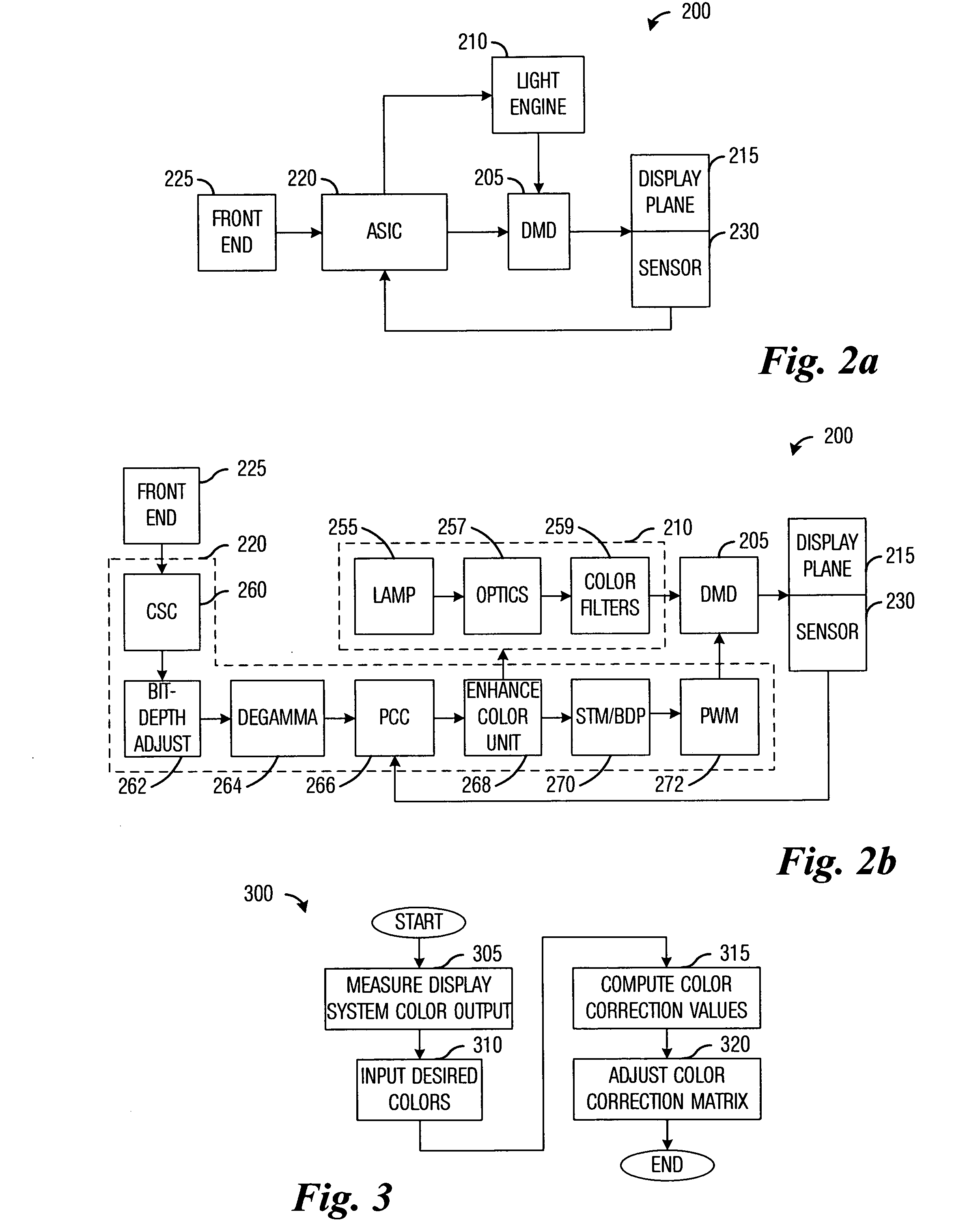
[0023]With reference now to FIG. 2a, there is shown a high level block diagram of a DMD-based display system 200, according to a preferred embodiment of the present invention. The di...


PUM

PropertyMeasurementUnit
colorsaaaaaaaaaa
coloraaaaaaaaaa
color spaceaaaaaaaaaa

Abstract

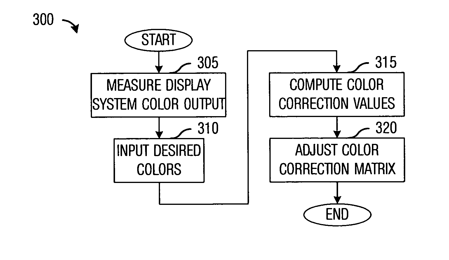
System and method for computing coefficients for color correcting rendered colors used in displaying images. A preferred embodiment comprises measuring color values of light output for a display system, receiving color values of desired colors, and computing a color correction matrix based on the measured color values and the input color values. The color correction matrix may be used to modify color commands to a light engine of the display system. The modifications to the color commands permit the storage and use of a set of color commands designed for a reference display system, simplifying display system design and manufacture.

Description

TECHNICAL FIELD[0001]The present invention relates generally to a system and a method for displaying images, and more particularly to a system and a method for computing coefficients for color correcting rendered colors used in displaying images.BACKGROUND[0002]When developing a display system for subsequent manufacture and sale, the display system manufacturer will often create a reference display system that is used to develop the display system hardware and software. The reference display system and its hardware and software are tweaked along with system settings, such as configuration parameters, conversion coefficients, and so forth, with the end result being a display system that meets image quality standards. Such a reference display system is commonly referred to as a “golden display system” or a “golden projector.”[0003]The golden projector's hardware, software, and tweaked system settings generally are used as the standard to which the subsequently manufactured display sys...

Claims


Application Information

Patent Timeline
Patent Type & Authority Patents(United States)
IPC IPC(8): G09G5/00G03F3/08G09G5/02H04N9/04H04N9/28H04N5/74G06K9/00G06K9/36H04N1/46G06K9/40
CPCG01J3/46G01J3/462G01J3/50G01J3/524G09G5/06G01J3/506G01J3/027G09G2320/0242G09G3/001
Inventor PETTITT, GREGORY S.RAMANATH, RAJEEV
Owner TEXAS INSTR INC
Learn More