Display device having stacked polarizers that differ in degrees of light absorbing bands and that are between a pair of protective layers such that no protective layer is located between the stacked polarizers
a display device and polarizer technology, applied in the direction of polarizing elements, instruments, optics, etc., can solve the problems of difficult to perform display with a higher contrast ratio by the method, high cost of polarizing plates with a higher degree of polarization, etc., to achieve high-performance display, reduce light leakage, and increase the contrast ratio of display devices
- Summary
- Abstract
- Description
- Claims
- Application Information
AI Technical Summary
Benefits of technology
Problems solved by technology
Method used
Image
Examples
embodiment modes
[0060]Hereinafter, embodiment modes and an embodiment of the present invention will be explained with reference to the drawings. Note that it is easily understood by those skilled in the art that forms and details of the invention can be variously changed without departing from the spirit and scope of the invention. Therefore, the present invention should not be construed as being limited to the content of the embodiment modes. Note that common portions and portions having similar functions are denoted by the same reference numerals in all diagrams for describing embodiment modes, and description thereof will not be repeated.
embodiment mode 1
[0061]In this embodiment mode, a concept of a display device in which a pair of stacked layers each including a polarizer using the present invention is provided will be explained.
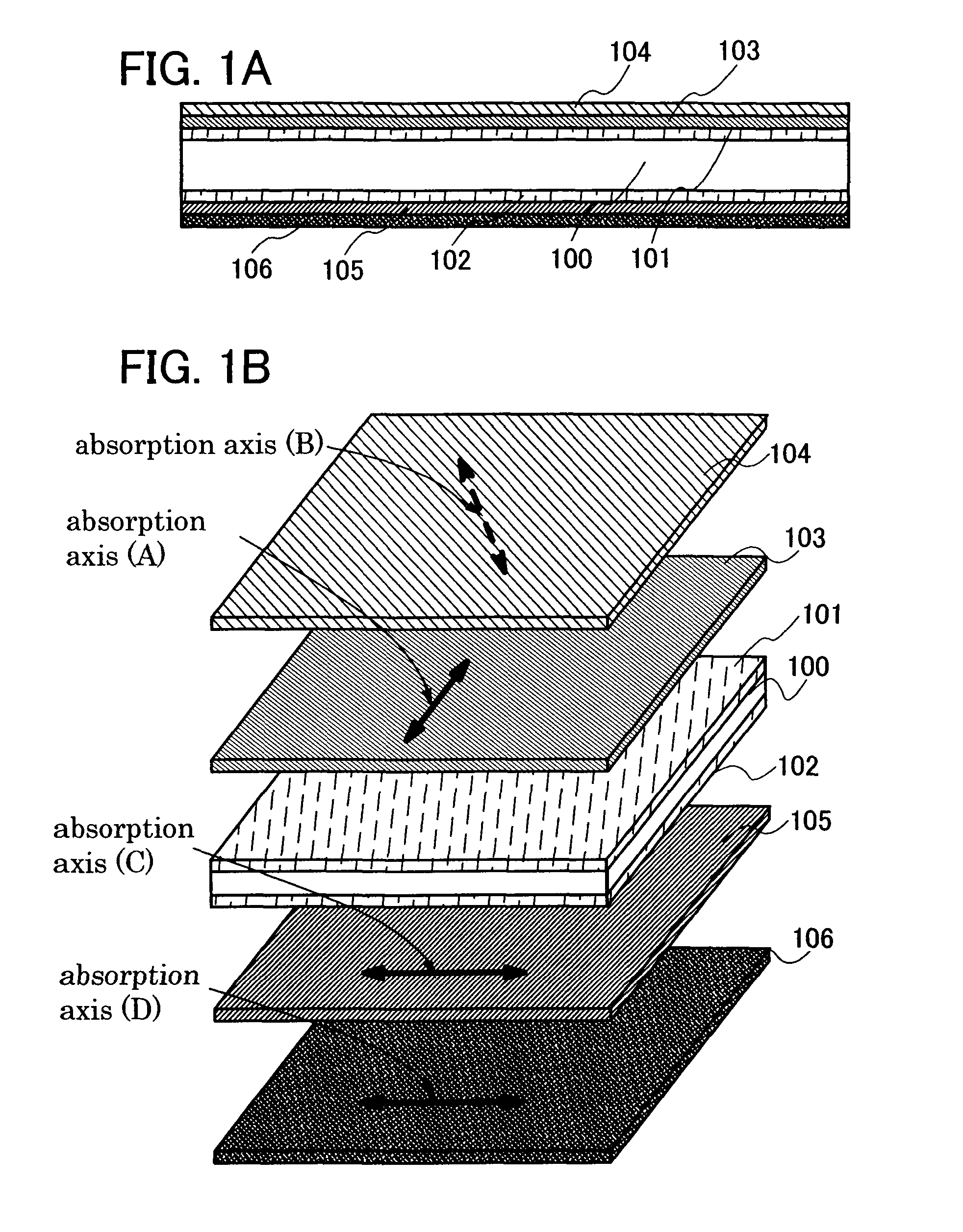
[0062]FIG. 1A is a cross-sectional view of a display device having a pair of stacked layers each including a polarizer, in which the wave length distributions of the extinction coefficients with respect to the absorption axes are different, and a structure in which at least one of the layers having the polarizers is disposed so as to be deviated from a parallel Nicols state. FIG. 1B is a perspective view of the display device. In this embodiment mode, an example of a liquid crystal display device having a liquid crystal element as a display element will be described.
[0063]As shown in FIG. 1A, a layer 100 having a liquid crystal element is sandwiched between a first substrate 101 and a second substrate 102 which are arranged so as to face each other.
[0064]In this embodiment mode, stacked layers each includi...
embodiment mode 2
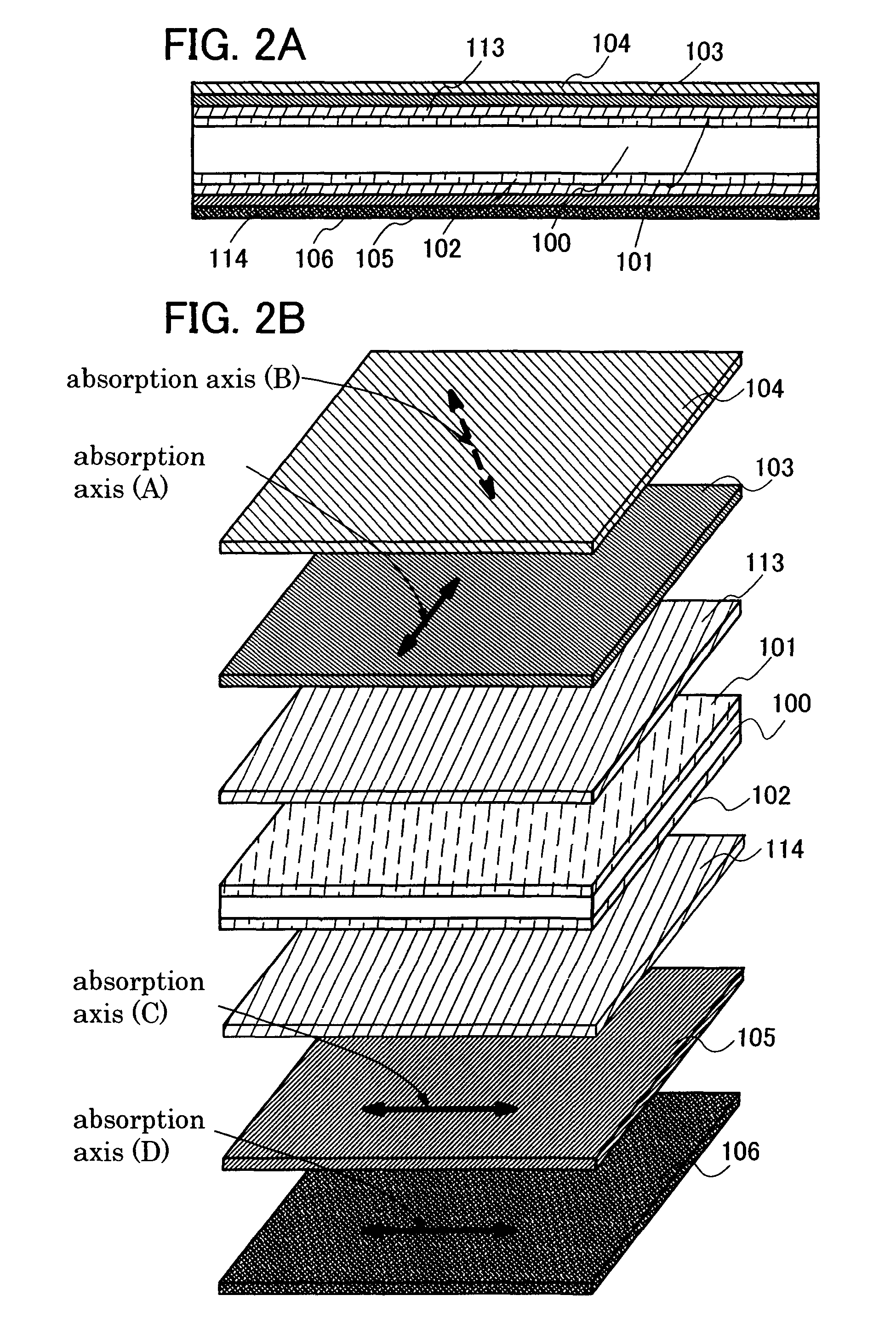
[0077]This embodiment mode will describe a concept of a display device provided with a retardation plate in addition to a pair of stacked layers each including a polarizing plate having a different wavelength distribution of extinction coefficient from each other with respect to the absorption axes unlike the above embodiment mode.
[0078]FIG. 2A is a cross-sectional view of a display device in which one of the pair of stacked layers each including a polarizer having a different wavelength distribution of extinction coefficient from each other with respect to the absorption axis is stacked to be deviated from a parallel Nicols state, and retardation plates are provided between the pair of stacked layers each including a polarizer and substrates respectively, while FIG. 2B is a perspective view of the display device. In this embodiment mode, a liquid crystal display device having a liquid crystal element as a display element will be explained as an example.
[0079]As shown in FIG. 2A, a ...
PUM
| Property | Measurement | Unit |
|---|---|---|
| size | aaaaa | aaaaa |
| size | aaaaa | aaaaa |
| wavelength | aaaaa | aaaaa |
Abstract
Description
Claims
Application Information
 - R&D
- Intellectual Property
- Life Sciences
- Materials
- Tech Scout
- Unparalleled Data Quality
- Higher Quality Content
- 60% Fewer Hallucinations
Browse by: Latest US Patents, China's latest patents, Technical Efficacy Thesaurus, Application Domain, Technology Topic, Popular Technical Reports.
© 2025 PatSnap. All rights reserved.Legal|Privacy policy|Modern Slavery Act Transparency Statement|Sitemap|About US| Contact US: help@patsnap.com


