Method and apparatus for providing an early warning of thermal decay in magnetic storage devices

a magnetic storage device and early detection technology, applied in the field of magnetic storage devices, can solve the problems of material becoming more susceptible to data loss, magnetic disks having only a thin layer of magnetic material are particularly susceptible to thermal decay, and information stored on the magnetic disk is more likely to be lost due to thermal decay

Inactive Publication Date: 2010-06-15
SEAGATE TECH LLC
View PDF17 Cites 6 Cited by
  • Summary
  • Abstract
  • Description
  • Claims
  • Application Information

AI Technical Summary

Benefits of technology

[0011]In accordance with the present invention, a method and an apparatus for providing an early warning of thermal decay in connection with magnetic storage media are provided. The present invention generally allows

Problems solved by technology

In addition, high data densities require magnetic material with a small grain size.
Accordingly, as the grain size and the layer thickness of the magnetic material has decreased, the material has become more susceptible to data loss due to thermal decay.
A magnetic disk having only a thin layer of magnetic material is particularly susceptible to thermal decay because the energy required to switch the magnetization of a portion of that disk is low.
As the anisotropic energy of each grain becomes nearer to the ambient thermal energy in a disk drive, information stored on the magnetic disk is more likely to be lost due to thermal decay.
Once the stored information decays beyond a threshold level, it will be impossible to properly read data written to the disk with the read head.
In particular, the loss in the amplitude of a signal produced in the transducer head will cause data to be lost

Method used


Image

  • Method and apparatus for providing an early warning of thermal decay in magnetic storage devices
  • Method and apparatus for providing an early warning of thermal decay in magnetic storage devices
  • Method and apparatus for providing an early warning of thermal decay in magnetic storage devices

Examples


Embodiment Construction

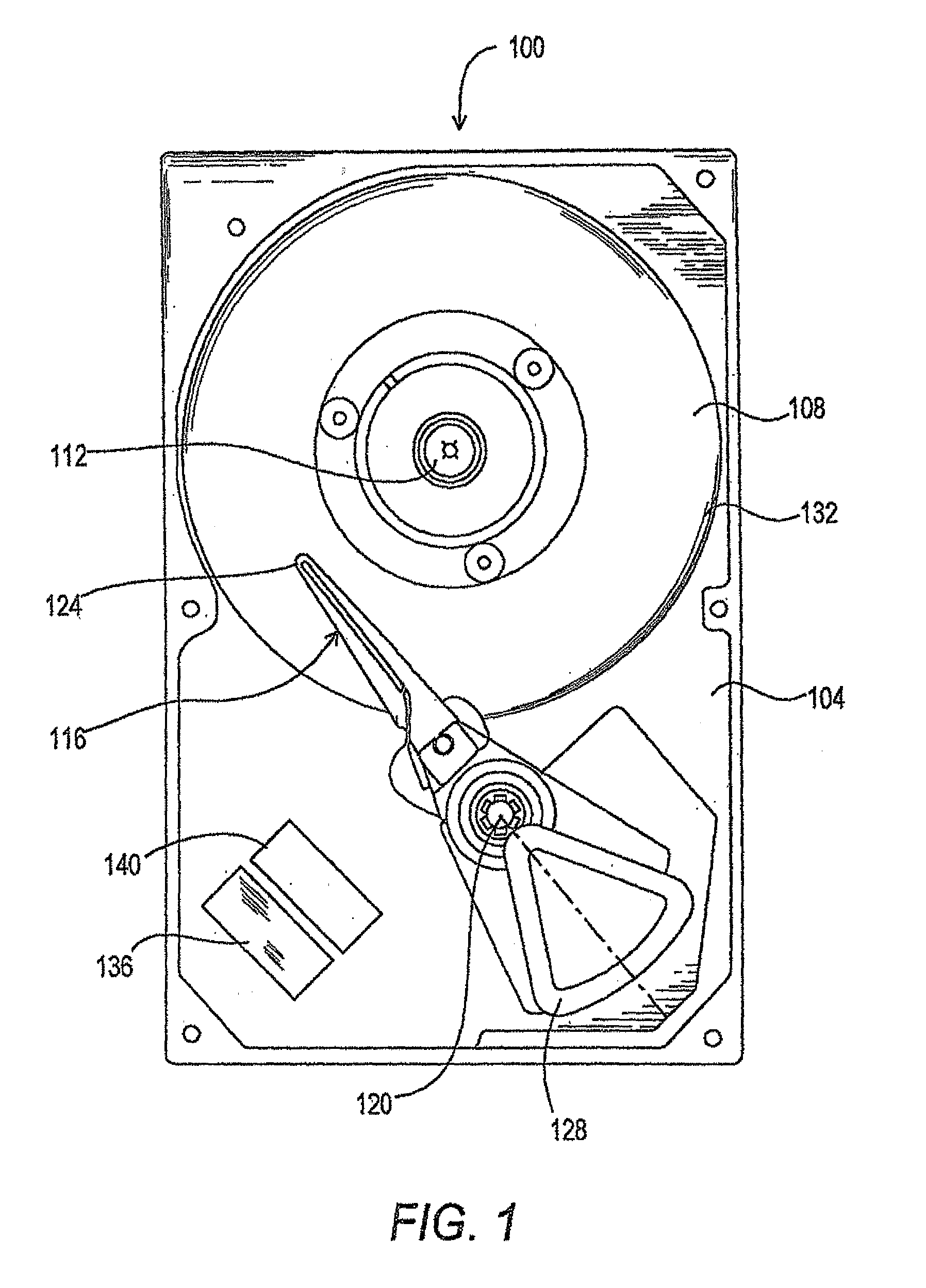
[0031]With reference now to FIG. 1, a typical disk drive 100 is illustrated. The disk drive 100 includes a base 104 and magnetic disks 108 (only one of which is shown in FIG. 1). The magnetic disks 108 are interconnected to the base 104 by a spindle motor (not shown) mounted within or beneath the hub 112 such that the disks 108 can be rotated relative to the base 104. The magnetic disk 108 is generally formed from a film of magnetically hard material deposited on a substrate. For example, the disk 108 may be formed by depositing a metal film on a rigid substrate.

[0032]Actuator arm assemblies 116 (only one of which is shown in FIG. 1) are interconnected to the base 104 by a bearing 120. Actuator arm assemblies 116 each include a transducer head 124 at a first end, to address each of the surfaces of the magnetic disks 108. The transducer heads 124 typically include read and write elements (not shown). A voice coil motor 128 pivots the actuator arm assemblies 116 about the bearing 120 ...


PUM


Abstract

A method and apparatus for providing an early warning of thermal decay in magnetic storage media are provided. In accordance with an embodiment of the present invention, a test pattern that is particularly susceptible to thermal decay is written to a disk. The test pattern is then read, and the amplitude of the signal produced by the test pattern is stored. When testing for thermal decay is desired, the test pattern is again read, and the amplitude of the signal produced in the channel is compared to the stored amplitude. If the later amplitude is less than the stored amplitude by at least a predetermined amount, a thermal decay warning signal is generated. In accordance with another embodiment of the present invention, a test pattern is written to a portion of a disk that has been identified as being particularly susceptible to thermal decay. The amplitude produced by the test pattern is then stored so that it can later be compared to an observed amplitude when testing for thermal decay. The present invention allows remedial measures to ensure the integrity of data to be taken before data loss due to thermal decay can occur.

Description

[0001]Priority is claimed from U.S. Provisional Patent Application No. 60 / 223,444, filed Aug. 4, 2000 entitled “METHODS OF EARLY WARNINGS FOR THERMAL DECAY IN MAGNETIC DEVICES,” which is incorporated herein by reference in its entirety.FIELD OF THE INVENTION[0002]The present invention relates to magnetic storage devices. More particularly, the present invention relates to the early detection of thermal decay in magnetic storage devices.BACKGROUND OF THE INVENTION[0003]Computer disk drives store digital information on magnetic disks. The magnetic disks are generally coated with a magnetic material capable of changing the direction of its magnetic orientation in response to an applied magnetic field. Information is stored on the magnetic disks as a series of magnetic transitions. Typically, the information is stored on each disk in concentric tracks that are divided into servo sectors and data sectors. Information is written to or read from a disk by a transducer head mounted on an ac...

Claims


Application Information

Patent Timeline
IPC IPC(8): G11B5/02
CPCG11B19/048
Inventor LIN, G. HERBERTGUARISCO, DAVIDCCHEW, XIAOKUN
Owner SEAGATE TECH LLC
Why Eureka
Try Eureka