Reproduction method, optical disk drive, and IC circuit

a technology of optical disk drive and reproduction method, which is applied in the direction of digital signal error detection/correction, instruments, recording signal processing, etc., can solve the problems of low-performance drive, increased possibility of causing such a problem of reproduction compatibility, and reproducing error

Inactive Publication Date: 2010-06-15
HITACHI LTD +1
View PDF9 Cites 5 Cited by
  • Summary
  • Abstract
  • Description
  • Claims
  • Application Information

AI Technical Summary

Benefits of technology

[0029]Firstly, the feature of the PRML method for an optical disk is explained. In the PRML method, a first bit string which has a constraint length or the length called a class bit number and a second bit string which has a target signal level corresponding to the first bit string and corresponds to the target signal level wherein the deviation from the regenerative signal is minimum are output as a result of binarization. A bit string of one bit shorter than a constraint length is called a state. Processing for transition at one time is carried out through transition processing from a state to the next state. In this case, there are basically two states at one time before the transition to the next state, and the basic procedure is to select from the two states only the state having a smaller integrated quantity (metric value) of the square of the difference between a target signal corresponding to the bit string relevant to each of the two states and the regenerative signal in the process (path) to transit into the aforementioned next state. If only one path out of the two paths is valid due to the limitation of the run length, transition is uniquely carried out without depending on the result of the comparison between the two integrated quantities of the squares of the differences. The code used in a DVD is a run length limited code having the minimum run length of 3 T. Therefore, in the PRML method for the replay of the DVD, the bit string wherein the run length is 1 T or 2 T is excluded beforehand. Thereby, it becomes possible to improve the performance so that a binarized result without run length limitation is not output and simultaneously to reduce the circuit size.
[0080](2-2) The method of executing binarization by the direct slice method and counting the number of data not conforming to the run length limitation. In the case of a DVD, attention may be focused only on 2 T data and the size of an additional circuit can be reduced. Further, by detecting the number of 2 T data for each PI frame zone, it is possible to equivalently count the number of row error. In this case, since the number of row error can be counted regardless of an error correction code, the degree of freedom in setting a standard responding to a speed increases. In addition, it is possible to execute verification judgment in an integrated manner from the results of the binarization by the PRML method and the count of the row error number.
[0082]As explained above, the present invention makes it possible to realize a reproduction method of executing appropriate verification in order to realize reproduction compatibility of an optical disk recorded with an optical disk drive capable of high speed record / reproduction with a previous generation optical disk drive employing the direct slice method, and an optical disk drive thereof.

Problems solved by technology

This is the case where, although an optical disk recorded with a novel high-performance drive is reproducible with a novel drive, reproduction error occurs when the optical disk is replayed with a conventional low-performance drive.
The possibility of causing such a problem of reproduction compatibility increases when a novel drive records data under the conditions that facilitate the reproduction with the novel drive itself.
A conventional technology has hardly been able to process verification properly in response to a higher speed and has not been able to assure the reproduction compatibility and prevent unnecessary record error and alternation processing from occurring.

Method used


Image

  • Reproduction method, optical disk drive, and IC circuit
  • Reproduction method, optical disk drive, and IC circuit
  • Reproduction method, optical disk drive, and IC circuit

Examples


first embodiment

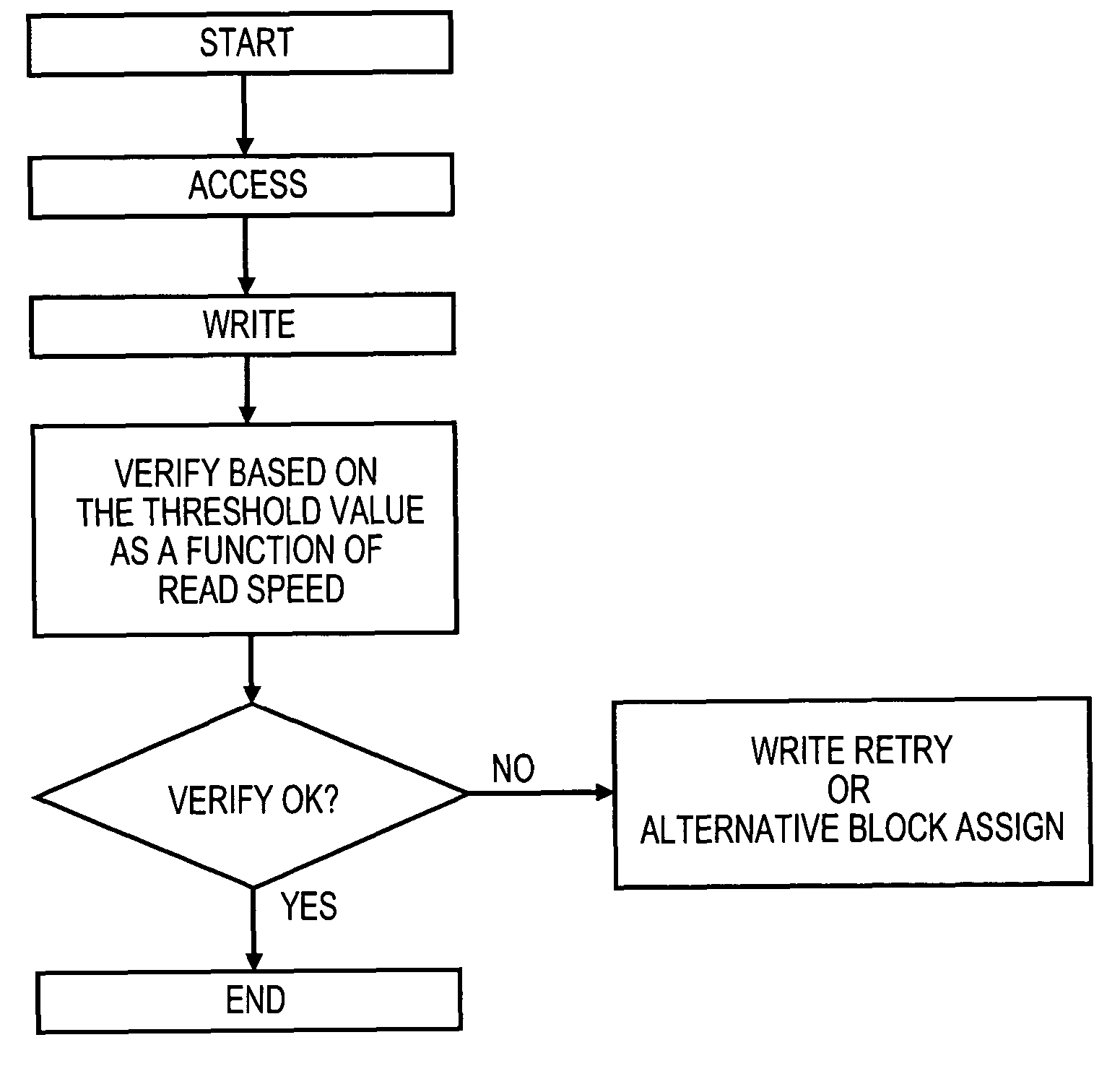
(Reproduction Method)

[0126]Experiment was carried out with an evaluator and a sample medium conforming to a 16×-speed DVD-RAM in order to examine the effectiveness of the aforementioned verification method of the present invention. The record was done at a 6×-speed, the reproduction was done by using the center track out of the five consecutive tracks while the reproduction speed and tilt conditions were changed, and jitter, PI error, the number of row error, the number of 2 T data, and others were measured.

[0127]FIG. 9 shows the actual measurement results of the relationship between tangential tilt and a jitter value. FIG. 10 shows the actual measurement results of the relationship between tangential tilt and PI error. The two binarization methods, the direct slice method and the PRML method, are compared with each other. It is understood that the PRML method shows higher performance. FIG. 11 shows the actual measurement results of the relationship between a read speed and a jitter...

second embodiment

(Circuit)

[0139]The configuration of a circuit suitable for the realization of an optical disk drive according to the present invention is hereunder explained on the basis of the drawings.

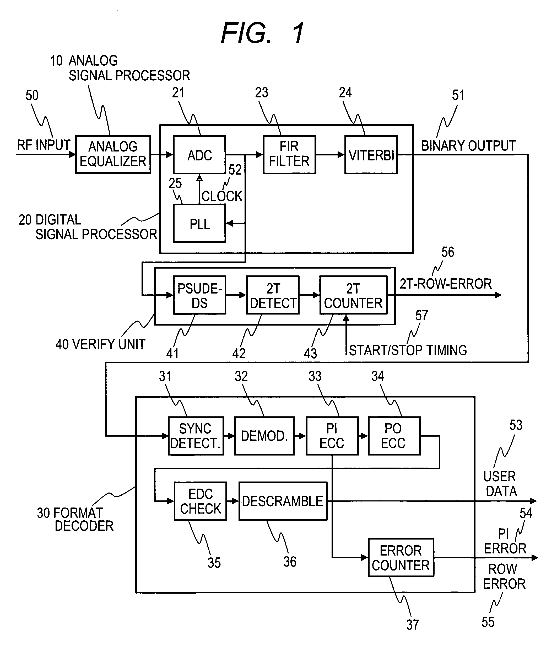
[0140]FIG. 1 is a block diagram showing a circuit configuration suitable for the implementation of the present invention. An RF signal 50 detected with an optical head not shown in the figure is subjected to equalization processing, AGC processing and others with an analog signal processor 10 and thereafter input into a digital signal processor 20. In the digital signal processor 20, the input RF signal is: converted into a digital signal for each clock with an AD converter 21; thereafter digitally equalized with an FIR filter 23; binarized with a Viterbi decoder 24; and ejected as a binarized signal 51. The internal structure of the Viterbi decoder 24 is not described here in detail because it exceeds the scope of the present invention but, just briefly, the Viterbi decoder 24 is a device to compar...

third embodiment

(Optical Disk Drive)

[0178]FIG. 42 is a view schematically showing an example of the configuration of an optical disk drive according to the present invention. An optical disk medium 100 is driven by a motor 160. At the time of reproduction, a laser power / pulse controller 120 controls the current supplied to a semiconductor laser 112 in an optical head 110 so that a light intensity directed by a CPU 140 can be secured and laser beam 114 is generated. The laser beam 114 is focused with an objective lens 111 and forms a light spot 101 on the optical disk medium 100. The reflected light 115 from the light spot 101 is detected with a photo-detector 113 through the objective lens 111. The photo-detector comprises a plurality of divided light-detecting components. A readout signal processor 130 reproduces information recorded on the optical disk medium 100 with the signal detected with the optical head 110. At the time of record, the laser power / pulse controller 120 converts prescribed rec...


PUM

PropertyMeasurementUnit
frequencyaaaaaaaaaa
run lengthaaaaaaaaaa
lengthaaaaaaaaaa

Abstract

In an optical disk drive that is equipped with a binarization circuit by the PRML method and carries out record / reproduction at a speed higher than a standard speed, to realize reproduction compatibility between the drive and another optical disk drive by the ordinarily adopted direct slice method. It can be realized by applying verification judgment equivalent to reproduction at a standard speed in accordance with a reproduction speed. More specifically, it is realized by counting 2 T data number by the direct slice method, using a Viterbi decoder that validates a run length shorter than the minimum run length, and adopting other measures. A higher record / reproduction speed is realized while reproduction compatibility, which is an important original function of an interchangeable optical disk, is secured.

Description

CLAIM OF PRIORITY[0001]The present application claims priority from Japanese application JP 2005-147491 filed on May 20, 2005, the content of which is hereby incorporated by reference into this application.CROSS REFERENCE TO RELATED APPLICATIONS[0002]U.S. patent application Ser. Nos. 10 / 933,321 and 11 / 092,872 are co-pending applications of this application. The contents of which are incorporated herein by cross-reference.FIELD OF THE INVENTION[0003]The present invention relates to an optical disk drive that forms record marks the physical properties of which are different from other parts on a recording medium and records information, a method for reproducing the information recorded in the medium, and an IC circuit.BACKGROUND OF THE INVENTION[0004]Optical disks are widely used in the forms of CDs and DVDs, the development of a next generation optical disk using blue laser has been advancing, and such an optical disk has been required to have a larger capacity. In addition, a super ...

Claims


Application Information

Patent Timeline
Patent Type & Authority Patents(United States)
IPC IPC(8): G11B20/14G11B7/00
CPCG11B7/00458G11B20/10009G11B20/10296G11B2020/10981G11B20/14
Inventor MINEMURA, HIROYUKI
Owner HITACHI LTD
Why Eureka
Try Eureka