Joining method for curved surfaces, and ultrasonic probe and manufacturing method thereof

a technology of curved surfaces and manufacturing methods, applied in the direction of mechanical vibration separation, instruments, catheters, etc., can solve the problems of deviation in sensitivity, misalignment of relative positions of flexible sheets and supports, and degrading the quality of ultrasonic images, so as to prevent the misalignment of ultrasonic transducers, the effect of preventing degradation of ultrasonic image quality and preventing the position of misalignmen

Active Publication Date: 2010-06-22
FUJIFILM CORP
View PDF15 Cites 0 Cited by
  • Summary
  • Abstract
  • Description
  • Claims
  • Application Information

AI Technical Summary

Benefits of technology

[0008]An object of the present invention is to provide a joining method for curved surfaces which can prevent the joining misalignment, and also to provide an ultrasonic probe which can prevent degradation of quality of ultrasonic images, and a manufacturing method of the ultrasonic probe.
[0014]According to the joining method of the present invention, since the concave-convex shapes of the curved member and the flexible member are corresponding to each other and engaged with each other to determine the relative positions of these members, the joining misalignment between the curved member and the flexible member is prevented.
[0016]According to the ultrasonic probe of the present invention, since the curved surface of the support and the joining surface of the flexible sheet have the concave-convex shapes which are corresponding to each other and engaged with each other, the joining misalignment between the support and the flexible sheet is prevented. Accordingly, the positional misalignment of the ultrasonic transducers is prevented, and the degradation of quality of the ultrasonic images is prevented because of few deviations in sensitivity and frequency band of ultrasonic.

Problems solved by technology

However, in the method of the Japanese Patent Laid-Open Publication No. 8-089505, it is possible that relative positions of the flexible sheet and the support are misaligned (joining misalignment) in joining these two parts.
Owing to this, misalignment of the ultrasonic transducers (positional misalignment) is caused, and quality of an ultrasonic image is degraded by deviation in sensitivity and frequency band of ultrasonic.

Method used


Image

  • Joining method for curved surfaces, and ultrasonic probe and manufacturing method thereof
  • Joining method for curved surfaces, and ultrasonic probe and manufacturing method thereof
  • Joining method for curved surfaces, and ultrasonic probe and manufacturing method thereof

Examples


Embodiment Construction

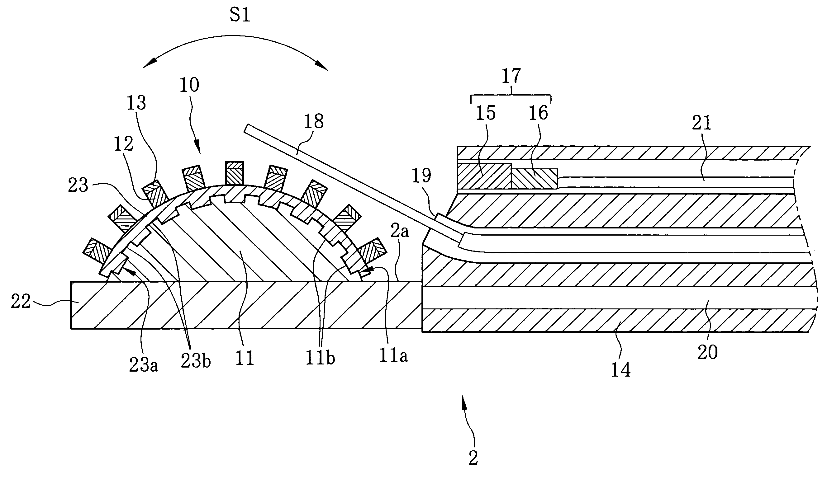
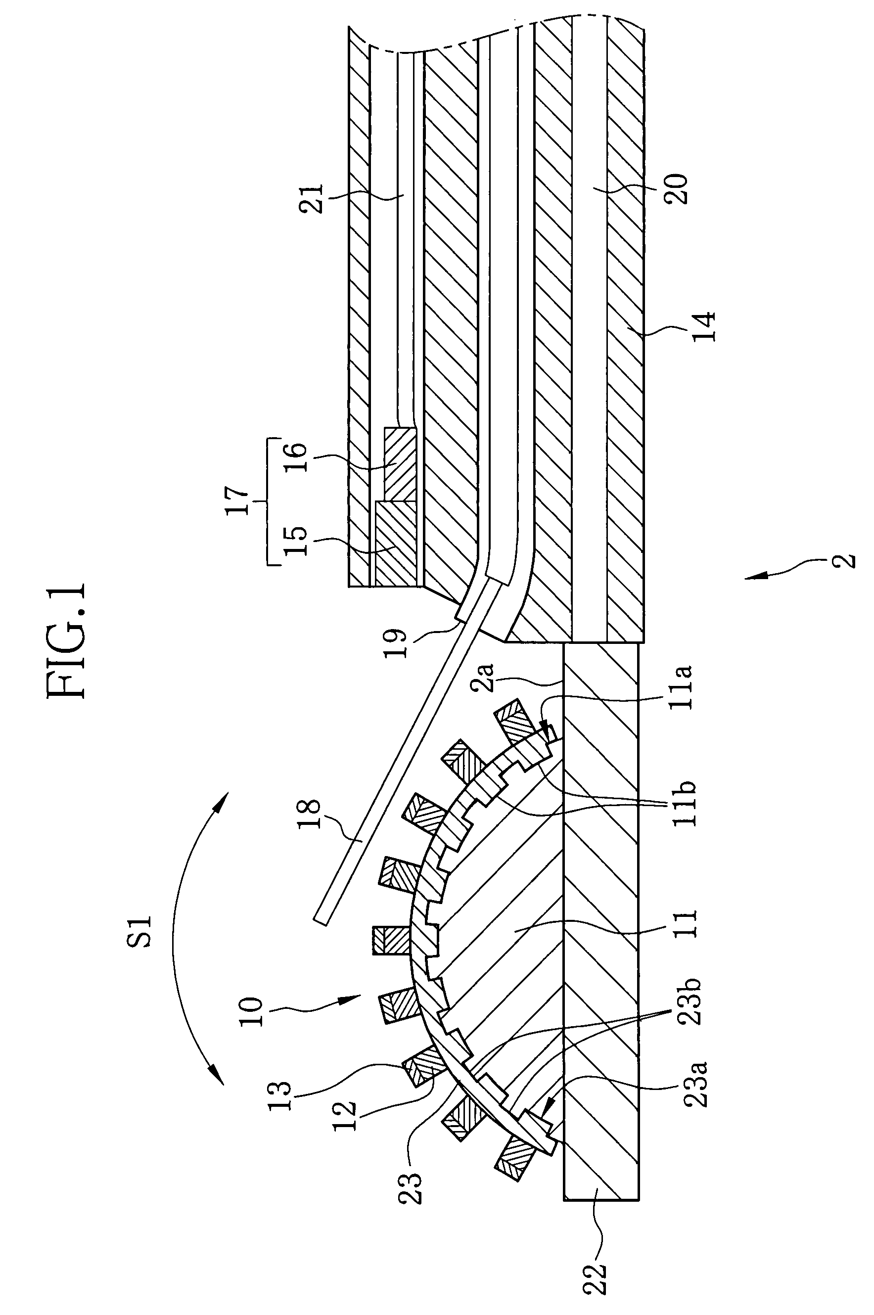
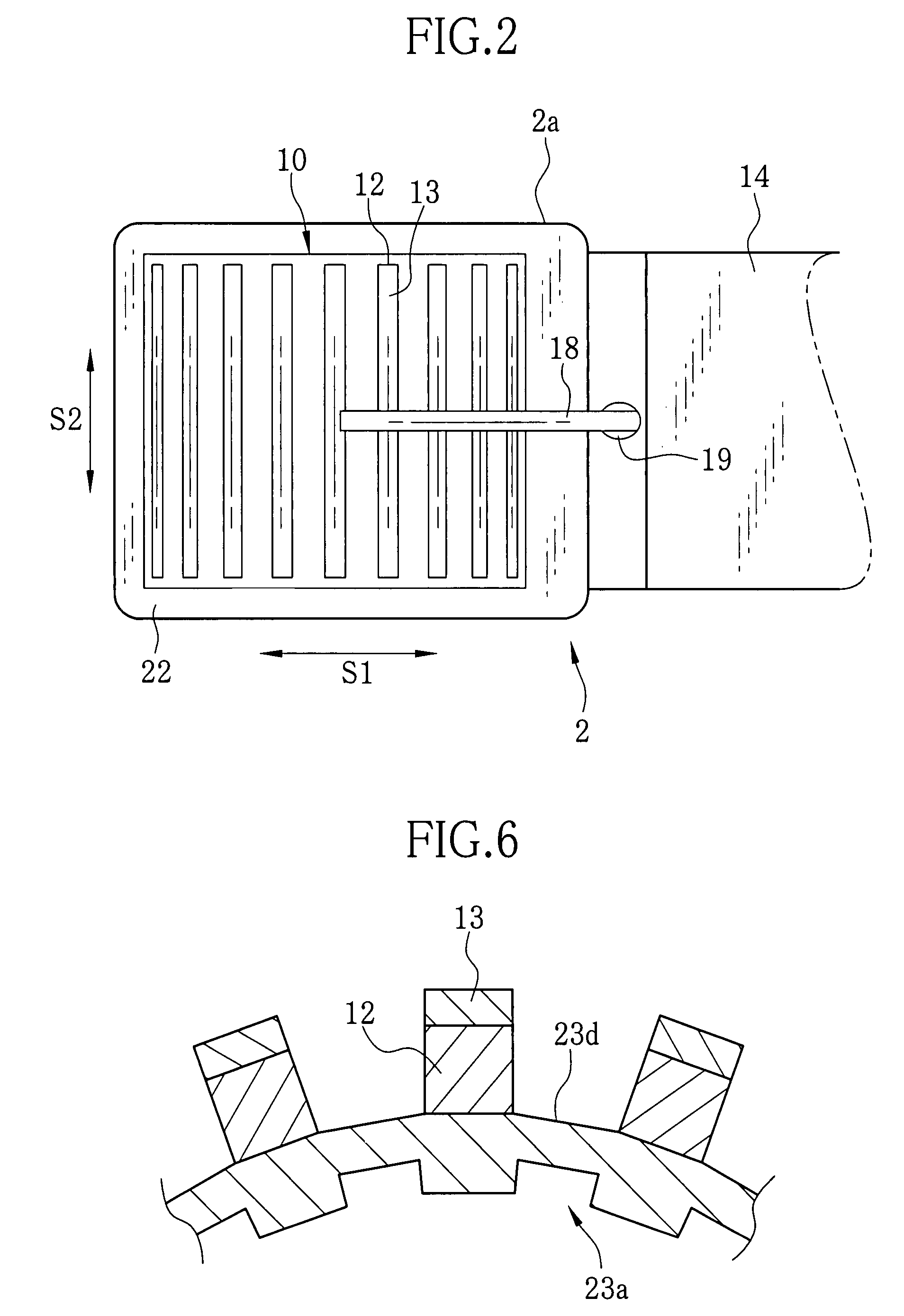
[0028]As shown in FIGS. 1 and 2, an ultrasonic probe 2 of a convex electronic scan mode according to the present invention is provided with an ultrasonic transducer array 10 disposed at a head 2a of the ultrasonic probe 2. In the ultrasonic transducer array 10, ultrasonic transducers 12 are arranged on a curved surface of a support 11 in a one-dimensional array form along a scan direction S1. A cross section of the support 11 along the scan direction S1 has a convex shape. The ultrasonic transducer 12 has a rectangular shape elongated in a slice direction S2, on which an acoustic matching layer 13 formed of epoxy resin or the like is attached.

[0029]An imaging device 17 is disposed at an upper portion of a sheath 14 connected to the head 2a. The imaging device 17 comprises an objective optical system 15 for receiving image light of a body part to be observed, and a CCD 16 for taking the image light to output image signals. A middle portion of the sheath 14 is provided with a channel ...


PUM

PropertyMeasurementUnit
flexibleaaaaaaaaaa
shapeaaaaaaaaaa
ultrasonicaaaaaaaaaa

Abstract

A head of an ultrasonic probe is formed by joining a flexible sheet holding a plurality of ultrasonic transducers to a curved surface of a support. Concave-convex shapes (concave-convex surfaces) are provided on the curved surface of the support and a joining surface of the flexible sheet. The concave-convex surfaces correspond to each other, and are engaged with each other to determine relative positions of the flexible sheet and the support when they are joined. Each of grooves on the concave-convex surface is positioned between adjacent ultrasonic transducers.

Description

BACKGROUND OF THE INVENTION[0001]1. Field of the Invention[0002]The present invention relates to a joining method for curved surfaces in which a flexible member is joined on a curved surface of a curved member, an ultrasonic probe used for ultrasonic diagnostics, and a manufacturing method of the ultrasonic probe.[0003]2. Description of the Related Arts[0004]In the medical field of recent years, a medical diagnosis utilizing ultrasonic images is put to practical use. The ultrasonic image is obtained by electrically detecting echo signals, which are sent from a biologic body, with an ultrasonic observing unit connected to an ultrasonic probe via a connector. The ultrasonic observing unit applies ultrasonic waves to a relevant part of the biologic body from the ultrasonic probe. A known mode for driving the ultrasonic probe is an electronic scan mode in which a plurality of ultrasonic transducers are disposed to transmit and receive the ultrasonic waves. In this mode, the ultrasonic t...

Claims


Application Information

Patent Timeline
Patent Type & Authority Patents(United States)
IPC IPC(8): G01N29/24H04R31/00
CPCA61B8/12B06B1/0633A61B8/445A61B8/4488A61B1/018A61B1/05Y10T29/49005
Inventor OOSAWA, ATSUSHI
Owner FUJIFILM CORP
Why Eureka
Try Eureka