
Apparatus and method for monitoring pressure related changes in the extra-thoracic arterial circulatory system

Active Publication Date: 2010-06-22
RIC INVESTMENTS LLC
View PDF31 Cites 79 Cited by
  • Summary
  • Abstract
  • Description
  • Claims
  • Application Information

AI Technical Summary

Benefits of technology

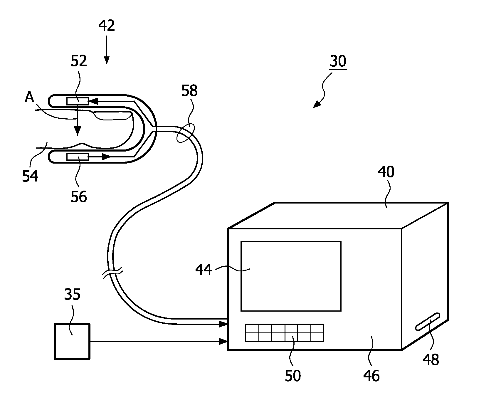
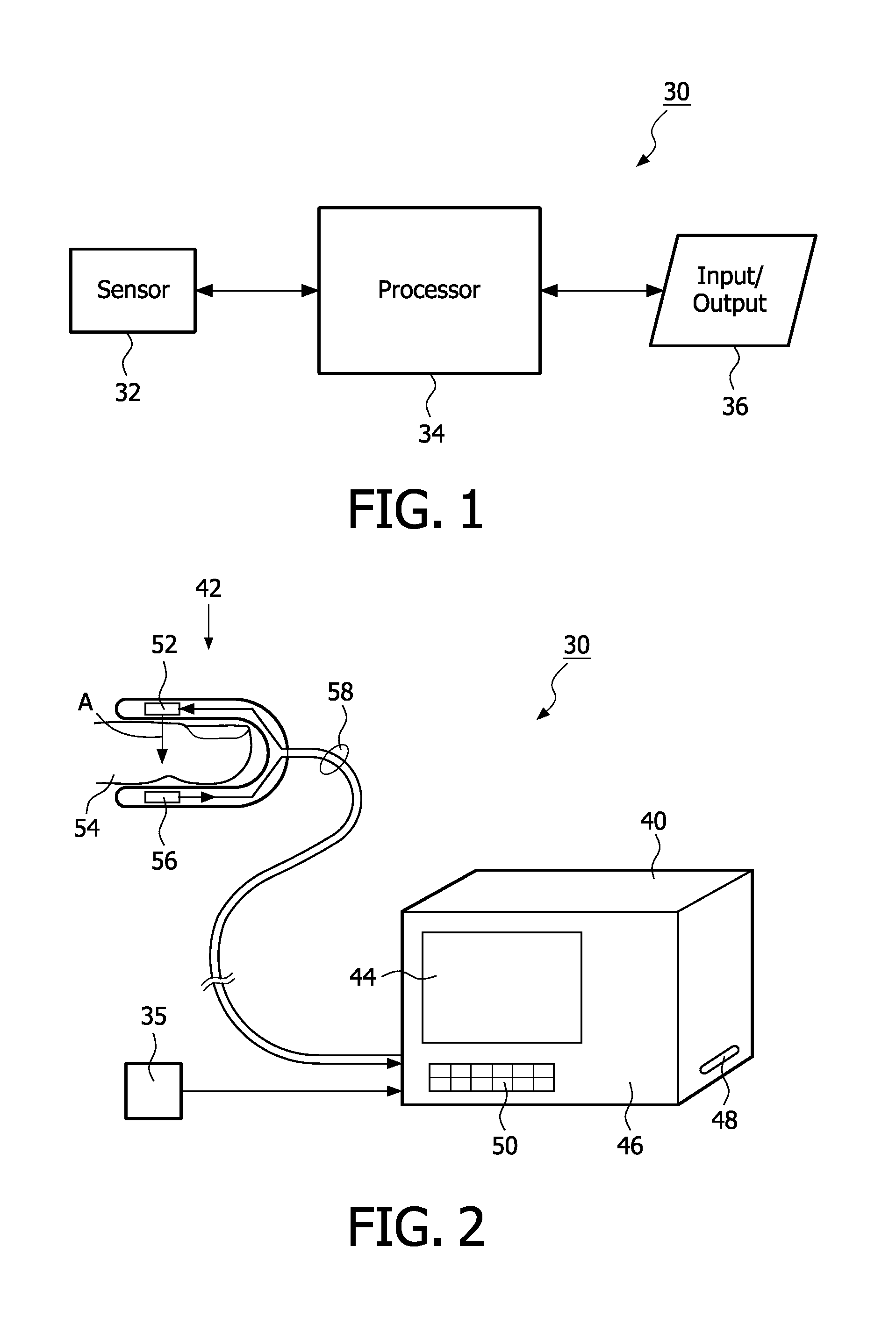
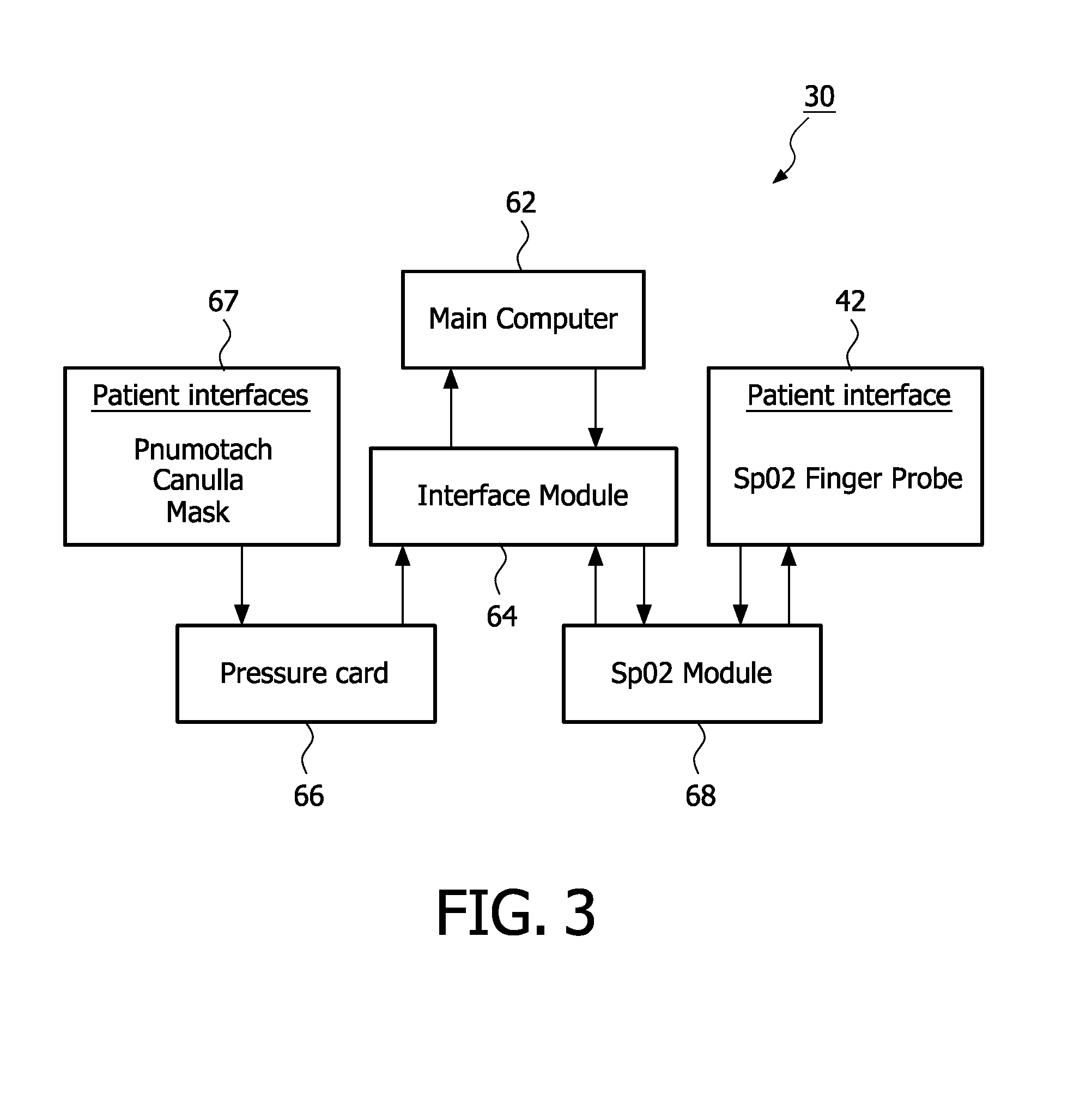
[0017]Accordingly, it is an object of the present invention to provide a cardio-pulmonary monitoring system that overcomes the shortcomings of conventional monitoring techniques. This object is achieved according to one embodiment of the present invention by providing an extra-thoracic monitoring system that includes a sensing means to detect a physiological characteristic of a patient associated with pressure changes in such a patient's circulatory system and for outputting a first signal indicative of such pressure changes. The system also includes a processing means to produce a thoracic pressure signal as a measure of such a patient's intra-thoracic pressure due to respiration. This is accomplished in the processing means by isolating breath related pressure variations in the first signal from the sensing means. This enables the patient's respiratory effort to be monitored.
[0020]It is yet another object of the present invention to provide a system and method for displaying patient information, which can be used alone or in combination with the pulmonary monitoring system or method and / or the FO2 / FIO2 monitoring system and method discussed above. The patient information display system includes means for determining fractional concentration of oxygen inhaled by a patient during one breathing cycle, means for measuring a pulse oximetry arterial oxygen saturation (SpO2) of such a patient, a display having a display area, and a display controller. This display controller causes a nomogram illustrating a relationship between the measured SpO2, the FIO2, and an estimated shunt, to be displayed in a first field on the display area. The nomogram shows the SpO2 on a first axis, the FIO2 on a second axis, and a plurality of curves. Each curve corresponds to a common estimated shunt percentage. The display controller causes an indicator to be displayed on the nomogram at a location defined by coordinates corresponding to a current value of the SpO2 and the FIO2. This provides a readily visible indication of the estimated shunt based on the measured SpO2 and the FIO2 values.
[0022]It is yet another object of the present invention to provide a method of monitoring the cardiac function of a patient that does not suffer from the disadvantages associated with conventional blood pressure monitoring techniques. This object is achieved by providing a method that includes: (1) passing light through a portion of the patient, (2) receiving light after having been passed through the patient, (3) outputting a first signal based on the received light, and (4) producing a cardiac pressure signal as a measure of the patient's vascular pressure due to cardiac function by isolating cardiac related pressure variations in the first signal. As noted above, this enables the present invention to monitor the patient's blood pressure non-invasively on a substantially continuous basis for detecting a symptom of a cardiac disorder.

Problems solved by technology

Many of these patient's are incapable of communicating effectively with their physician, for example they may be too young, incapacitated in some way, or have a mental deficiency that prevents effective communication with their caregivers.
However, this requires attaching the patient to the ventilator.
These methods are invasive and, therefore, have limited application.
In the ICU, a significant number of patients are at high risk for respiratory failure or have recently been extubated.
This determination is very difficult to make because the determination will be different for each patient.
Without an objective measurement of the hemodynamic effect, this determination cannot be made.
Thus, they are not suited to detect the dynamic blood pressure changes associated with these blood pressure related symptoms of heart disease.
However, conventional continuous blood pressure monitors are invasive; requiring locating a pressure sensor within the patient's arterial circulatory system.

Method used


Image

  • Apparatus and method for monitoring pressure related changes in the extra-thoracic arterial circulatory system
  • Apparatus and method for monitoring pressure related changes in the extra-thoracic arterial circulatory system
  • Apparatus and method for monitoring pressure related changes in the extra-thoracic arterial circulatory system

Examples


Embodiment Construction

[0047]Mammals displace blood from within the thorax to the extra-thoracic circulation with each heartbeat and with each breath. The displacement of blood from the thorax by the heart is due to the volumetric discharge of blood from the heart into the arterial system, and, in particular, into the aorta. For example, the work of the heart changes the pressure of the blood in the thoracic vessels relative to that in the systemic circulation. In addition, respiration or breathing also causes a pressure change in the thorax, and, hence, displacement of blood from the thorax to the extra-thoracic circulation. For purposes of the present invention, the changes in volumetric discharge of blood from the heart that cause a measurable distention of the extra-thoracic arterial circulation and the pressure changes in the thorax that occur during each heartbeat and during each respiratory cycle that also cause a measurable distention of the extra-thoracic arterial circulation are collectively ref...


PUM


Abstract

A method and apparatus for monitoring changes in the intra-thoracic pressure of a patient due to the patient's respiratory activity or volumetric changes in the extra-thoracic arterial circulatory system due to cardiac function based on the changes in pressure in the patient's extra-thoracic arterial circulatory system as measured by a plethysmography sensor, such as an photoplethysmograph. A frequency spectrum is generated for the plethysmograph signal and the frequencies of interest is isolated from the frequency spectrum by setting appropriate cutoff frequencies for the frequency spectrum. This isolated frequency is used to filter the plethysmograph signal to provide a signal indicative of the patient's respiratory activity or cardiac function. For corrections for breathing frequency roll-off and deviations of the I:E ratio from 1:1.

Description

CROSS-REFERENCE TO RELATED APPLICATIONS[0001]This application claims priority under 35 U.S.C. § 119(e) from provisional U.S. patent application No. 60 / 525,954 filed Dec. 1, 2003, the contents of which are incorporated herein by reference.BACKGROUND OF THE INVENTION[0002]1. Field of the Invention[0003]The present invention pertains to a method and apparatus for monitoring changes in the intra-thoracic pressure of a patient due to the patient's respiratory activity or cardiac function, and, in particular, to a first technique in which pleural pressure changes due to respiratory effort are monitored based on the changes in pressure in the patient's extra-thoracic arterial circulatory system, and to a second technique in which a patient's vessel distention in the extra-thoracic arterial circulatory system due to respiratory activity or cardiac function are monitored.[0004]2. Description of the Related Art[0005]Numerous patients arrive at a hospital's emergency room each day complaining ...

Claims


Application Information

Patent Timeline
IPC IPC(8): A61B5/08
CPCA61B5/0205A61B5/087A61B5/725A61B5/7257A61B5/0082A61B5/02416A61B5/0816A61B5/021A61B5/02427A61B5/1455
Inventor STARR, ERIC W.SCULL, JAMES A.AYERS, ERICHETE, BERNIE F.WILCZEK, DONALD S.SANDERS, MARK H.
Owner RIC INVESTMENTS LLC
Learn More