Multi-beam modulator for a particle beam and use of the multi-beam modulator for the maskless structuring of a substrate

a multi-beam modulator and beam technology, applied in the direction of electrodes and associated parts, particle separator tubes, radiation therapy, etc., can solve the problems of high cost, high production cost, and inability to realize mandatory dosing steps, etc., to avoid elaborate, cost-intensive steps and reduce exposure productivity.

Inactive Publication Date: 2010-06-22
VISTEC ELECTRON BEAM
View PDF17 Cites 106 Cited by
  • Summary
  • Abstract
  • Description
  • Claims
  • Application Information

AI Technical Summary

Benefits of technology

[0018]The invention has the advantage that it avoids the elaborate, cost-intensive steps of producing exposure masks. However, the time-serial writing principle reduces the productivity of the exposure compared to parallel structure transfer using masks. Therefore, a line of development for maskless exposure devices consists in multiplying the effective writing speed though a large quantity of partial beams operating in parallel. The partial beams are arranged in the form of an array and can be switched on and off individually by a special modulation element (controllable beam sources, blanker, mirror). The present inventive solution describes the construction of a multibeam modulator based on row-oriented shift registers and its concept of dose control. The multibeam modulator can be configured with respect to the minimum memory requirement of the electronic circuit, with respect to the temporal and spatial homogenization of the entirety of the beam, and with respect to beam-optical and thermal factors. Further, it relates to proposed solutions enabling error redundancy and dose correction through the ability to reconfigure the control.
[0019]The multibeam modulator has the advantage that the density of openings within a row is distributed in an inhomogeneous manner. Extremes in the total current of all partial beams are prevented in this way. The openings within a row are equidistant, but the distance between the openings, expressed as a quantity of cells, is less than the quotient of the number of cells of a row and the number of openings within a row.

Problems solved by technology

However, because of the large quantity of leads, the number of beams operating in parallel is limited to about 1000 and enables only a moderate increase in productivity in spite of the extensive resources employed.
The main defect in known implementations of this principle is the limiting to one bit (on / off) per exposure cycle and row, so that mandatory dosing steps, proximity corrections, and the like can only be realized to a limited extent through the use of a plurality of arrays.
Known solutions for the blanking chip require a high storage density and lack flexibility.

Method used


Image

  • Multi-beam modulator for a particle beam and use of the multi-beam modulator for the maskless structuring of a substrate
  • Multi-beam modulator for a particle beam and use of the multi-beam modulator for the maskless structuring of a substrate
  • Multi-beam modulator for a particle beam and use of the multi-beam modulator for the maskless structuring of a substrate

Examples


Embodiment Construction

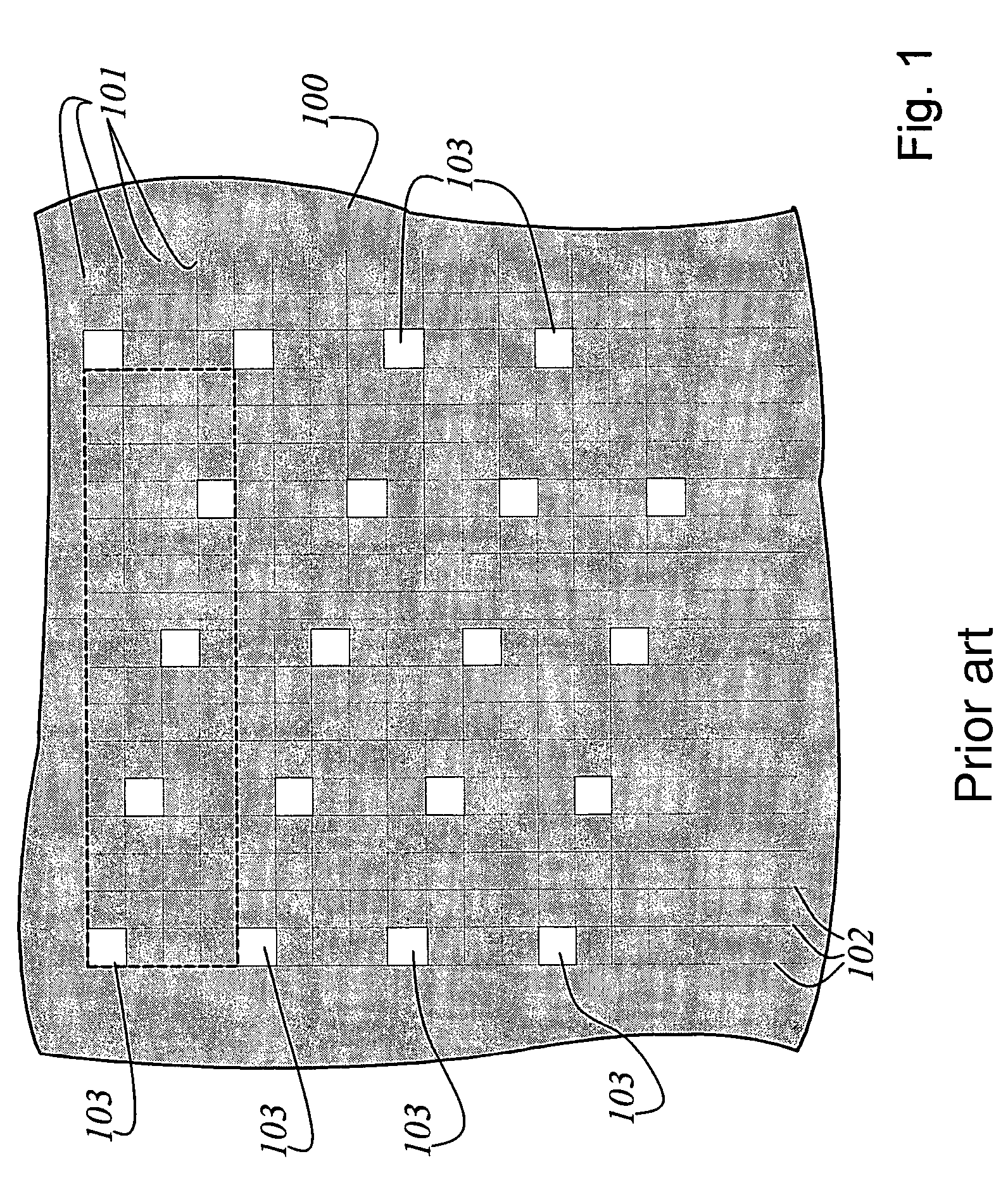
[0039]FIG. 1 shows an aperture plate 100 according to the prior art. In this aperture plate 100, n rows 101 with m cells and m columns 102 with n cells are formed. In each row 101, a determined quantity k of openings 103 is formed. The openings 103 are distributed within a row such that the density of the openings 103 within a row is identical.

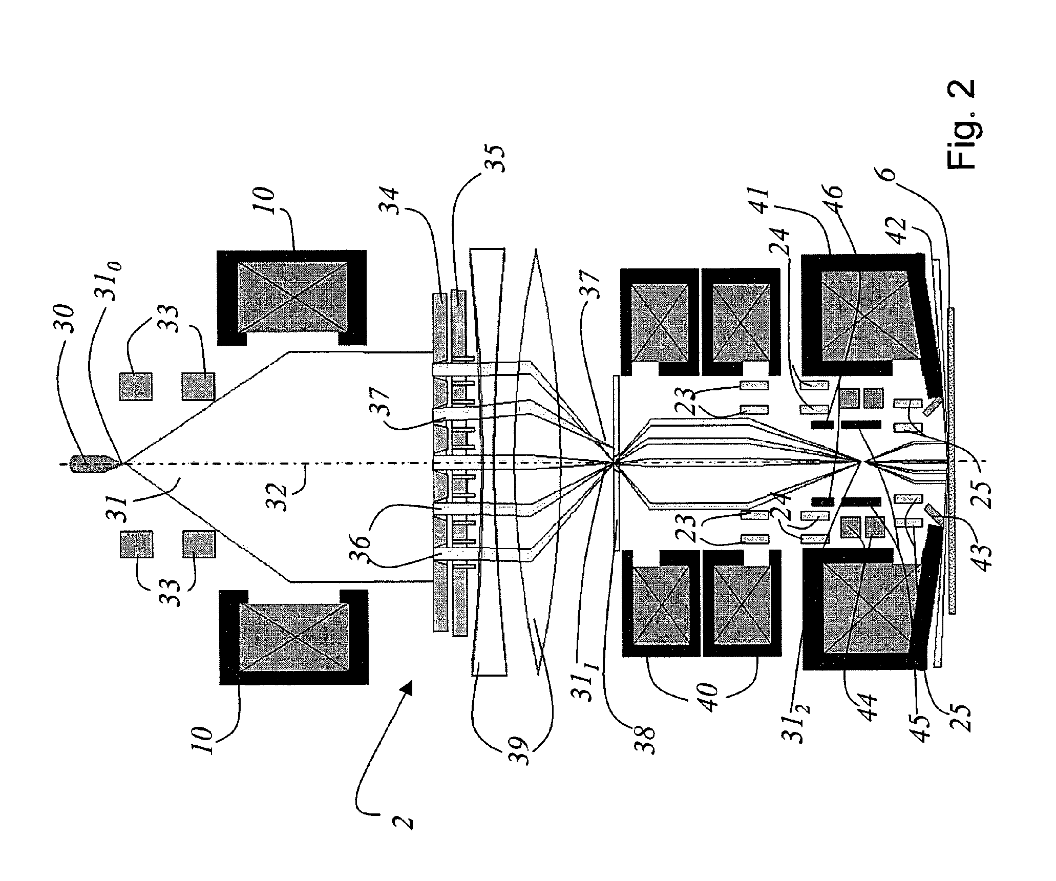
[0040]FIG. 2 shows a schematic view of the construction of a total system for maskless electron beam lithography. Although the following description is limited to electron beams, this should not be construed as a limitation of the invention. The invention is, of course, suited to all particle beams.

[0041]An electron beam 31 is generated by an electron gun 30 and propagates in direction of an electron-optical axis 32. The electrons exiting from the electron gun 30 have a source crossover 310. Downstream of the electron gun 30 is a beam centering device 33 which orients the electron beam symmetrically around the optical axis 32. After the beam c...


PUM


Abstract

The invention discloses a multibeam modulator which generates a plurality of individual beams from a particle beam. The particle beam illuminates the multibeam modulator at least partially over its surface. The multibeam modulator comprises a plurality of aperture groups composed of aperture row groups. The totality of all aperture rows defines a matrix of m×n cells, where m cells form a row, and k openings are formed in each row. The density of openings within a row is inhomogeneously distributed.

Description

CROSS-REFERENCE TO RELATED APPLICATIONS[0001]This application claims priority of International Application No. PCT / EP2005 / 055521, filed Oct. 25, 2005 and German Application No. 10 2004 052 994.9, filed Nov. 3, 2004, the complete disclosures of which are hereby incorporated by reference.BACKGROUND OF THE INVENTION[0002]a) Field of the Invention[0003]The invention is directed to a multibeam modulator for a particle beam. In particular, the invention is directed to a multibeam modulator which generates a plurality of individual beams from a particle beam. The particle beam illuminates the multibeam modulator at least partially over its surface. The multibeam modulator comprises a plurality of aperture groups, each aperture group having a plurality of aperture row groups. The totality of all aperture rows defines a matrix of m×n cells, where m cells form a row and k openings are formed in each row.[0004]b) Description of the Related Art[0005]The invention is further directed to the use ...

Claims


Application Information

Patent Timeline
Patent Type & Authority Patents(United States)
IPC IPC(8): G21K1/02
CPCB82Y10/00B82Y40/00H01J37/3177H01J2237/31774H01J2237/0437
Inventor DOERING, HANS-JOACHIMHEINITZ, JOACHIM
Owner VISTEC ELECTRON BEAM
Why Eureka
Try Eureka