Radiofrequency plasma spark plug

a plasma spark plug and radiofrequency technology, applied in spark plugs, sparking devices, basic electric elements, etc., can solve the problems of difficult control of spark plug ignition, large-sized sparks generated by spark plugs from small potential differences, etc., and achieve the effect of increasing the probability of the mixture surrounding the spark plug being ignited

Inactive Publication Date: 2010-06-22
RENAULT SA
View PDF11 Cites 14 Cited by
  • Summary
  • Abstract
  • Description
  • Claims
  • Application Information

AI Technical Summary

Benefits of technology

[0014]In this context, one object of the present invention is therefore to provide a spark plug which, once assemb...

Problems solved by technology

Igniting a fuel-lean mixture is, however, difficult to control.
Such...

Method used


Image

  • Radiofrequency plasma spark plug
  • Radiofrequency plasma spark plug

Examples


Embodiment Construction

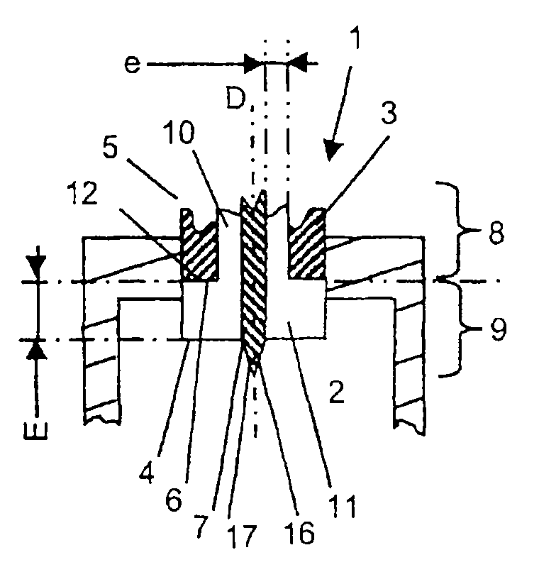
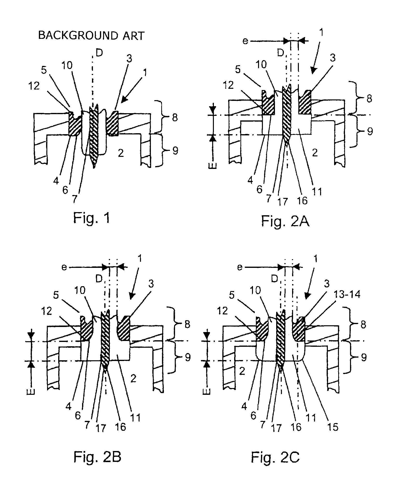
[0046]The spark plug 1 of FIG. 1 is a spark plug developed by the Applicant Company to be used as a plasma-generating spark plug. This spark plug is covered by patent applications which at the date of filing of the current application had not yet been published.

[0047]This spark plug comprises a cylindrical central electrode 7 of the axis of symmetry D of which a portion, termed the internal portion 8, is positioned inside and some distance from an annular shell 3 which has the form of a cylindrical tube of axis D, and another portion, termed the external portion 9, which is positioned on the outside of annular shell 3.

[0048]An insulating component of annular shape is also positioned partly inside the annular shell, around the central electrode, so as to separate the shell from the central electrode 7. The insulating component, the central electrode and the shell 3 are components which exhibit symmetry of revolution about the axis D. The external portion 9 of central electrode 7 has ...


PUM


Abstract

A radiofrequency plasma spark plug configured to equip a combustion chamber including: an annular shell with a main axis; a central electrode made of a conductive material, extending along the main axis and including an inner portion arranged inside the annular shell and an outer portion arranged outside the annular shell; an annular electrically insulating part extending at least about the inner portion of the central electrode so as to be interposed between the shell and the electrode, the insulating part only covering part of the outer portion of the central electrode. The insulating part includes an annular flange concealing the entire circular terminal surface of the shell relative to the uncovered part of the electrode.

Description

BACKGROUND OF THE INVENTION[0001]I. Field of the Invention[0002]The present invention relates in general to radiofrequency plasma spark plugs.[0003]More specifically, the invention relates to a spark plug, known as a radiofrequency plasma spark plug, intended to equip a combustion chamber of an internal combustion engine, and comprising:[0004]an annular shell of main axis D formed in a first conducting material and having first and second ends and an end circular surface with a main axis of symmetry D located at the first end of the shell;[0005]a central electrode formed in a second conducting material extending along the main axis D and comprising an internal portion positioned inside said annular shell and an external portion positioned on the outside of said annular shell, nearer to the first end of the shell than to the second;[0006]an electrically insulating component of annular shape extending at least around the internal portion of the central electrode such as to be inserted...

Claims


Application Information

Patent Timeline
IPC IPC(8): H01T13/20
CPCH01T13/52H01T13/50
Inventor JAFFREZIC, XAVIERAGNERAY, ANDRE
Owner RENAULT SA
Why Eureka
Try Eureka