Signal line driver circuit, light emitting device and driving method thereof

a technology of signal line driver and light emitting device, applied in the direction of static indicating device, instruments, optics, etc., can solve the problem of extremely difficult arrangement to be realized, and achieve the effect of suppressing the influence of tfts characteristics variation

Inactive Publication Date: 2010-06-22
SEMICON ENERGY LAB CO LTD
View PDF146 Cites 18 Cited by
  • Summary
  • Abstract
  • Description
  • Claims
  • Application Information

AI Technical Summary

Benefits of technology

[0044]In the present invention, when performing the setting operation, the video signal is used to specify a current source circuit disposed in an arbitrary column from among the first column to the last column. In addition, the current source circuit is specified only in an arbitrary period. Thus, a current source circuit requiring the setting operation can be specified among current source circuits disposed in a plurality of columns. Further, since the setting operation can be performed spending time for the specified current source circuit, the setting operation can be precisely performed.
[0046]In the current source circuits disposed in the plurality of columns, setting operations for the current source circuits may be sequentially performed from the first column to the last column. However, when setting operations are not sequentially performed for the current source circuits from the first column, but the setting operations can be performed at random for the current source circuits, various advantages are exhibited. For example, a sufficient time can be arbitrarily used to perform the setting operation for the current source circuit. Further, in the case where periods during which the setting operation can be performed are dotted in one frame, when an arbitrary column can be selected, the degree of freedom is increased, and a setting operation period can be set long. For example, in the period during which the setting operation can be performed and which is dotted in one frame, the setting operation can be performed for the one-column current source circuit by making full use of the period. One of other advantages is that the influence of charge leakage in a capacitor element disposed in the current source circuit can be made inconspicuous. Thus, when a defect has occurred in accordance with the setting operation, the defect can be made inconspicuous.
[0047]According to the present invention, the video signal is used to control the current source circuit, thereby obviating the necessity of dedicated circuits to perform control of the setting operation for the current source circuit and specification of the current source circuit. Consequently, since the number of circuits to be disposed is reduced, the defect-occurrence ratio in the manufacture can be minimized, and the yield can be improved. In addition, since the number of circuits to be disposed can be reduced, the layout area can be reduced. Thus, the frame area can be reduced, and the device can be miniaturized.
[0050]The present invention provides a signal line driver circuit including the current source circuit described above. Further, the present invention provides a light emitting device capable of suppressing the influence of variation in characteristics of TFTs constituting both pixels and driver circuits to enable a desired signal current Idata to be supplied to light emitting elements by using pixels each having a circuit structure not influenced by the TFT characteristics.

Problems solved by technology

However, such arrangement is extremely difficult to be realized.

Method used


Image

  • Signal line driver circuit, light emitting device and driving method thereof
  • Signal line driver circuit, light emitting device and driving method thereof
  • Signal line driver circuit, light emitting device and driving method thereof

Examples


embodiment mode 1

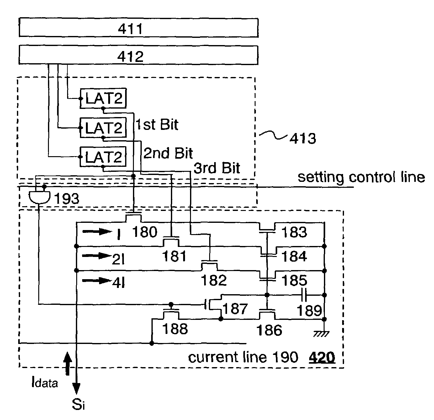
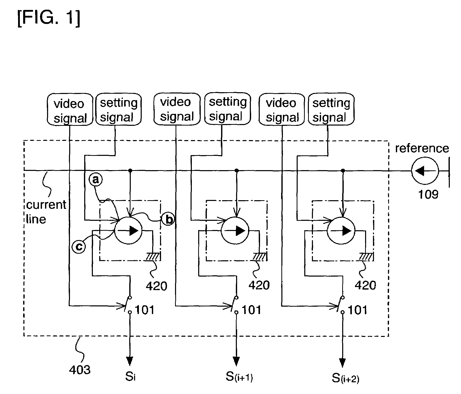
[0139]In this embodiment mode, a description will be made of an example of a circuit structure of a current source circuit 420 shown in FIG. 1, which is provided in a signal line driver circuit of the present invention.

[0140]Referring to FIG. 1, a setting signal input from a terminal a corresponds to a video signal supplied from a second latch circuit 413. However, since the video signal is also used to control a pixel, the video signal is not directly input to the current source circuit 420, but input thereto via a logical operator. The logical operator enables switching between the case of using the video signal to control the pixel (to display an image) and the case of using the video signal to control the current source circuit. Specifically, the setting signal input from the terminal a corresponds to the signal supplied from an output terminal of the logical operator that is connected to a setting control line (not shown in FIG. 1). The present invention performs setting of the...

embodiment mode 2

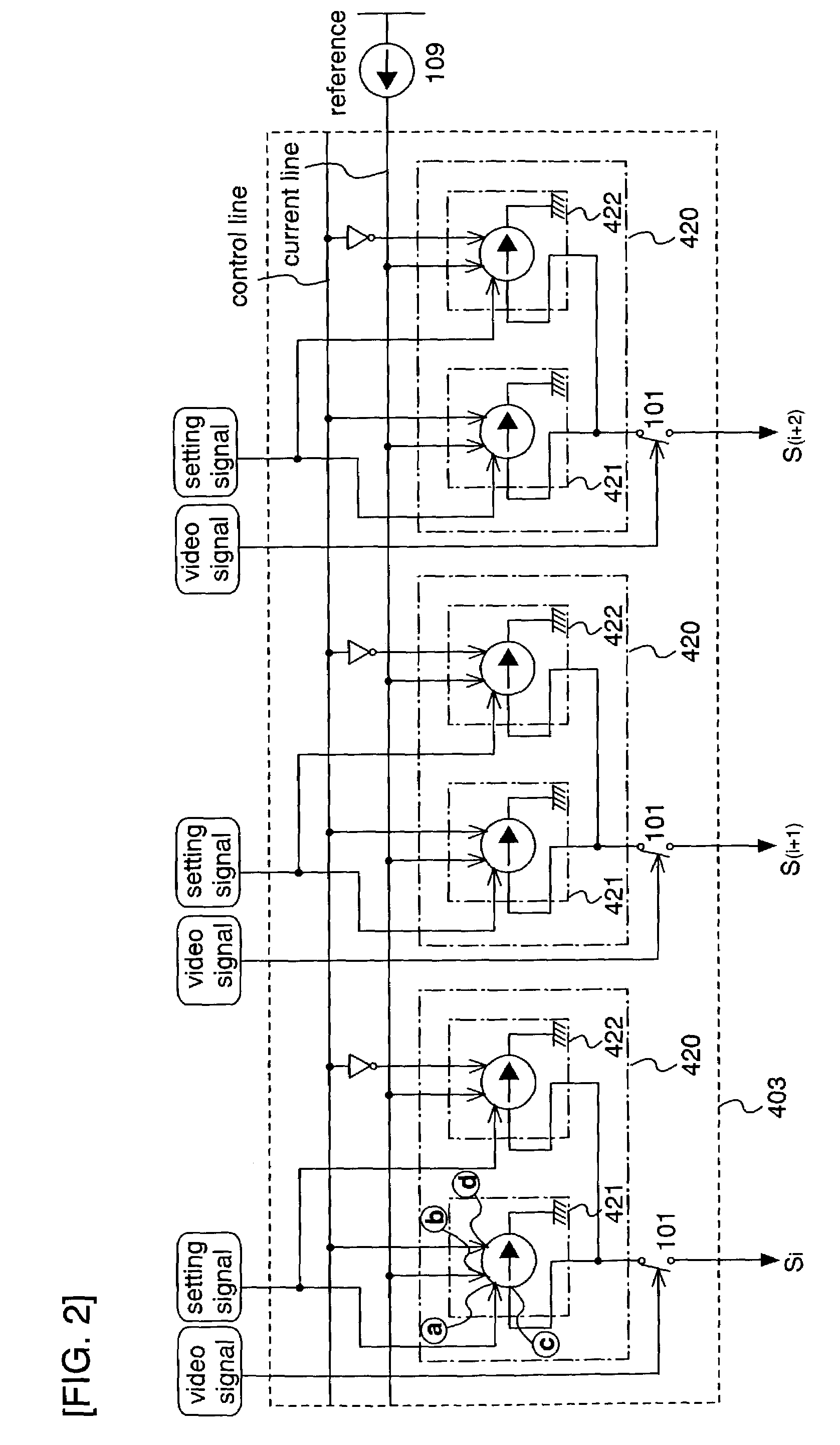
[0221]The above has described that, for the current source circuit shown in FIG. 19 (or, FIG. 6(B), 40(B), 42(A), or the like), preferably, two current source circuits are provided for each signal line (each column), in which one of the current source circuits is used to perform the setting operation, and the other current source circuit is used to perform the setting operation. This is because the setting operation and the input operation cannot be performed simultaneously. In this embodiment mode, the structure and operation of either the first current source circuit 421 or the second current source circuit 422 shown in FIG. 2 will be described with reference to FIG. 8.

[0222]Note that the signal line driver circuit includes the current source circuit 420, the shift register, the latch circuits, and the like.

[0223]In the present invention, a setting signal input from a terminal a corresponds to a video signal supplied from a second latch circuit 413. That is, the setting signal in ...

embodiment mode 3

[0238]In this embodiment mode, the structure of a light emitting device including the signal line driver circuit of the present invention will be described using FIG. 15.

[0239]Referring to FIG. 15(A), the light emitting device includes a pixel portion 402 including a plurality of pixels arranged in matrix on a substrate 401, and includes a signal line driver circuit 403 and first and second scanning line driver circuits 404 and 405 in the periphery of the pixel portion 402. While the signal line driver circuit 403 and the two scanning line driver circuits 404 and 405 are provided in FIG. 15(A), the present invention is not limited to this. The number of driver circuits may be arbitrarily designed depending on the pixel structure. Signals are supplied from the outside to the signal line driver circuit 403 and the first and second scanning line driver circuits 404 and 405 via FPCs 406.

[0240]The structures and operations of the first and second scanning line driver circuits 404 and 405...


PUM


Abstract

Variation occurs in transistor characteristics. The present invention relates to a signal line driver circuit comprising a plurality of current source circuits respectively corresponding to a plurality of wirings, characterized in that: the plurality of current source circuits each comprise capacitor means and supply means; and the plurality of current source circuits each convert a supplied current into a voltage in accordance with a video signal, and supply a current corresponding to the converted voltage.

Description

TECHNICAL FIELD[0001]The present invention relates to a technique of a signal line driver circuit. Further, the present invention relates to a light emitting device including the signal line driver circuit.BACKGROUND ART[0002]Recently, display devices for performing image display are being developed. Liquid crystal display devices that perform image display by using a liquid crystal element are widely used as display devices because of advantages of high image quality, thinness, lightweight, and the like.[0003]In addition, light emitting devices using self-light emitting elements as light emitting elements are recently being developed. The light emitting device has characteristics of, for example, a high response speed suitable for motion image display, low voltage, and low power consumption, in addition to advantages of existing liquid crystal display devices, and thus, attracts a great deal of attention as the next generation display device.[0004]As gradation representation method...

Claims


Application Information

Patent Timeline
Patent Type & Authority Patents(United States)
IPC IPC(8): G09G5/10G09G5/00G09G3/20G09G3/32
CPCG09G3/3266G09G3/3283G09G3/2022G09G3/2077G09G3/3241G09G3/325G09G2310/027G09G2300/0426G09G2300/0842G09G2300/0852G09G2300/0861G09G2310/0216G09G2310/0262G09G3/3291G09G3/30G02F1/133
Inventor KIMURA, HAJIME
Owner SEMICON ENERGY LAB CO LTD
Why Eureka
Try Eureka