Transport system for container processing machines

a technology for processing machines and transportation systems, applied in the field of transportation systems, can solve the problems of unfavorable cleaning of the floor, the shape of the duct carrier in the form of an arc of a circle, and the inability to change the configuration of the star, which is not variable and fixed by the support plate, so as to facilitate the cleaning of the floor

Active Publication Date: 2010-06-29
KRONES AG
View PDF15 Cites 29 Cited by
  • Summary
  • Abstract
  • Description
  • Claims
  • Application Information

AI Technical Summary

Benefits of technology

[0007]The support housings, which can be in the shape of slender torpedoes, are positioned and stabilized via connecting struts inside the star configuration in such a manner that the stars are in their operatively required positions. Here, either adjacent support housings are connected each by one connection strut and / or at least one support housing is connected to the machine substructure. The connection interfaces and the connection struts, however, can form various chosen star configurations, because they can be compatible if desired, and they allow the addition or removal of support housings or stars as a function of the given application. Because no physical processing table is provided, and to form sufficiently large free spaces around the support housing down to the floor, hygienically perfect microbiological conditions can be achieved, and the cleaning cycles can be run effectively and rapidly. In fact, the arrangement is a modular construction set system, within which one can assemble components or modules that have at least one connection interface as needed to form a virtually stable processing table transport system, which avoids the drawbacks that to date had to be tolerated with the physical processing table. This column-beam system allows an optimal variability with regard to any desired star wheel configurations. The design concept of the transport system allows particularly advantageously the removal of a star with defective function, completely with the support housing, and its replacement by a similar star, without having to remove or modify the appropriate positions of the other stars.
[0009]The connection struts, with the exception of their length and optionally their wall thicknesses, present at least substantially the same construction, with regard to the external dimensions, and are preferably identical. Using one construction set of connection struts having different lengths, which optionally may have large wall thicknesses in the case of components or modules of higher weight, many different star configurations can be used using the connection interfaces. In the process, the connection struts, some of which may even be solid profiles, should present an external circumference which ensures that, in the mounted position, no horizontal or deep surfaces on the top side are formed, but only surfaces that are as smooth as possible, from which liquids can easily run off. They can be U-shaped profiles in rotated arrangement or closed hollow profiles having a great variety of profiles, each presenting as small a width as possible in the viewing direction towards the floor, to achieve high stability or rigidity.
[0012]Although, for many support housings, a single connection interface would be sufficient, in the case of support housings that are, for example, a part of a system component in an end position, it would be advantageous for each support housing to present at least two connection interfaces, preferably with circumferential offset, to allow modular expansion possibilities or reduction possibilities for the transport system with a high degree of freedom. The connection interfaces, in the case of a support housing with at least two connection interfaces, are advantageously offset by an angle which is different from 180°, advantageously by approximately 126°, about the axis of the support housing. This arrangement allows a space-saving zig-zag arrangement, which can be advantageous for the joint working of adjacent stars.
[0013]The transport system is stiffened on one side by the connection struts and optionally connected to the machine, where, in an advantageous embodiment, each support housing presents only one standing leg which rests on the floor. The standing leg can be arranged directly on the support housing, or it can be connected to the connection strut which is connected to the support housing. In an advantageous embodiment, the standing leg of the support housing is arranged with offset with respect to the column axis, so that a large, free, lower support housing opening is usable, for example, for heat removal and / or for the control of, or replacement work on, parts located in the interior. The standing leg can be slender and designed with standing surface that is as small as possible, to facilitate the cleaning of the floor, and to interfere as little as possible in the free space around the support housing on the floor.
[0018]In an advantageous embodiment, the interfaces—joining places are at least substantially flat transitions, and preferably they are even packed and / or sealed, so that no dirt becomes fixed there, that is so that the cleaning can be carried out easily.
[0027]By a standardization of the connection struts, which are used for integrating these modules in the star configuration, a universal modular component system with high variability is achieved. A subsequent modification or completion of an already existing installation is possible without any problems and at low cost.

Problems solved by technology

This concept is being questioned today, for microbiological reasons and because it is difficult to clean.
Although this concept is slightly better than the previous processing table solutions with regard to microbiological conditions and cleaning, the support plate nevertheless covers an unnecessarily large floor area, and, between the hoods there are intersecting areas and angles in which dirt becomes fixed.
Furthermore, the star configuration, which is not variable and fixed by the support plate, is a drawback; in fact, it is tailored so to speak to each given application.
Different numbers and types of stars can be chosen depending on the application, nevertheless, the shape of the duct carrier in the form of an arc of a circle does not allow any variability worth mentioning.
The concept is also not satisfactory from the microbiological point of view.

Method used


Image

  • Transport system for container processing machines
  • Transport system for container processing machines
  • Transport system for container processing machines

Examples


Embodiment Construction

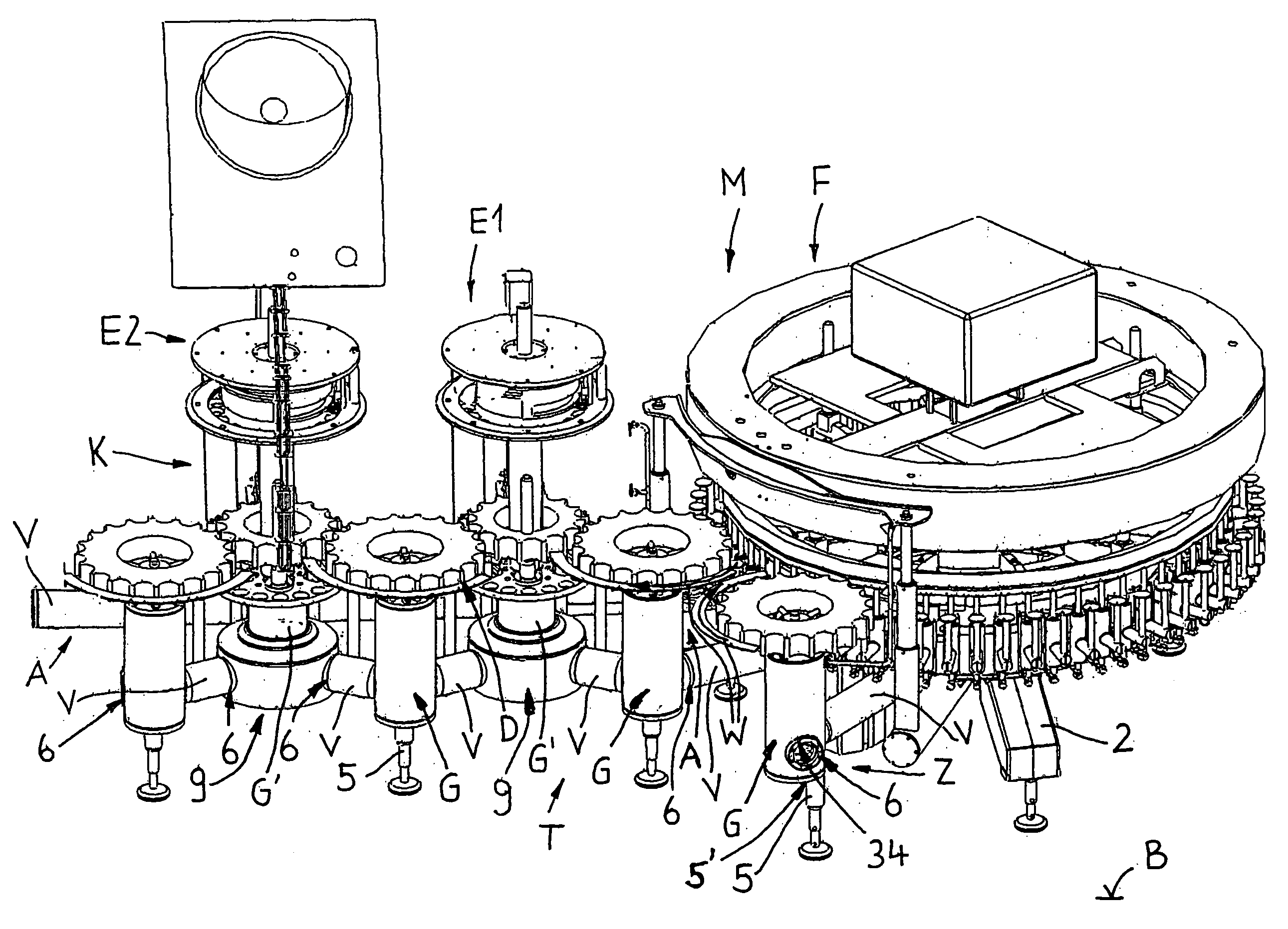
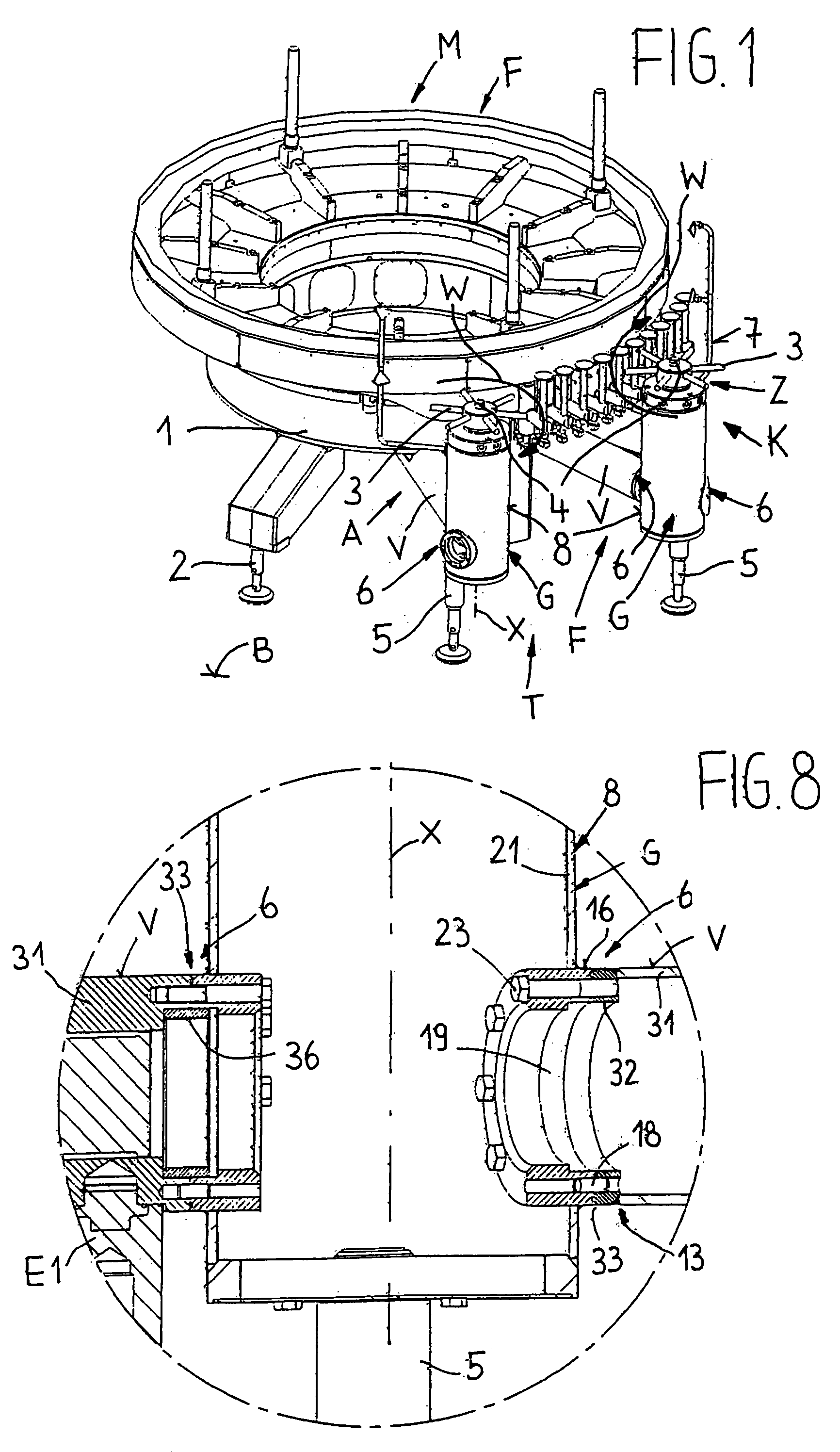
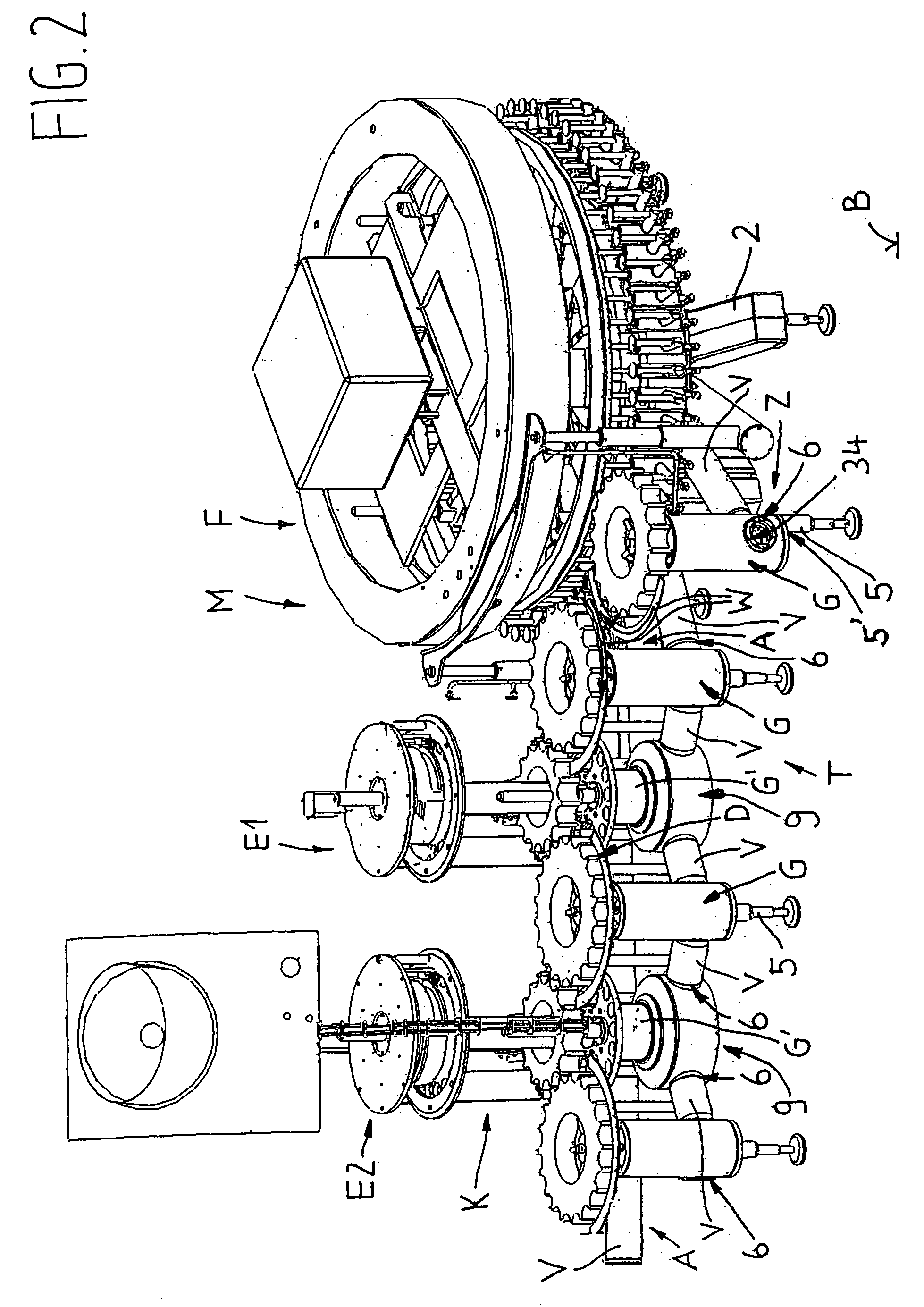
[0039]FIG. 1 shows a container processing machine M using the example of a bottle filler F (shown without top boiler part), with which a transport system T consisting of an inlet star Z and an outlet star A is functionally associated in a star configuration K, in such a manner that the transport paths W of the stars A, Z are linked with the circumferential path of the machine M. In the star configuration, the stars A, Z are at approximately the same distance from the machine on the floor B, in a delimited circumferential area of the machine M. Of the stars A, Z, only the support structure fragments 3 are shown, to simplify, to which the container-transporting elements are attached in the usual manner.

[0040]The machine M presents a substructure 1, which stands with the brackets and support feet 2 on the floor B. Each star A, Z is arranged on the upper part of a support housing G, which carries a drive shaft 4 that can be rotated. Each support housing G is shaped in the shape of a col...


PUM


Abstract

A transport system for container processing machines, particularly for bottle fillers, with inlet and outlet stars, which can be driven and are arranged on columnar support housings, and define a star configuration, in which the inlet and outlet stars define container transport paths which are linked with the machine. Each support housing presents at least one, preferably lateral, connection interface, to which a joining end of a connection strut is attached, in a removable manner. The other joining end of the connection strut is connected, in a detachable manner, to a connection interface of an additional support housing or of a machine substructure. In each case, in such manner, the star configuration can be changed as desired in a modular manner.

Description

CROSS-REFERENCE TO RELATED APPLICATION[0001]This is the U.S. national stage under 35 U.S.C. §371, of international application no. PCT / EP2006 / 000791, having an international filing date of Jan. 31, 2006, and claims priority to German application no. 20 2005 002 470.8 filed on Feb. 16, 2005.FIELD OF THE DISCLOSURE[0002]The disclosure relates to a transport system used in container processing machines, such as for bottling operations.BACKGROUND OF THE DISCLOSURE[0003]Container processing machines, such as, bottle fillers, in the past presented a processing table which was firmly attached to the machine and in which the inlet and outlet stars, and optionally transfer stars, were built in with a fixed mutual arrangement and also a fixed arrangement with respect to the machine. This concept is being questioned today, for microbiological reasons and because it is difficult to clean. Furthermore, the star configuration is established and not variable, i.e., tailored to fit a given applicat...

Claims


Application Information

Patent Timeline
Patent Type & Authority Patents(United States)
IPC IPC(8): B65B43/42B65B59/04B65C9/00B67C3/02B67C3/22B67C3/24B67C7/00
CPCB67C3/22B67C7/004B67C7/002
Inventor WEINBRENNER, VOLKERACHHAMMER, KARL-HEINZLAUMER, ROLANDBIELMEIER, HEINRICH
Owner KRONES AG
Why Eureka
Try Eureka