Method for operating to brake gear of a vehicle

a technology for operating brakes and gears, which is applied in the direction of brake action initiation, brake systems, mechanical devices, etc., can solve the problems of significant increase in the cost of the brake arrangement and the complexity of the electrically-mechanical actuating unit, and achieve the effects of low power, low reduction/transmission ratio, and limited brake force to be generated by the parking brake system

Inactive Publication Date: 2010-06-29
LUCAS AUTOMOTIVE GMBH
View PDF25 Cites 43 Cited by
  • Summary
  • Abstract
  • Description
  • Claims
  • Application Information

AI Technical Summary

Benefits of technology

[0009]The advantage of the invention is that the brake forces to be generated by the parking brake system can be limited. Limited, for example, to the extent that it is only necessary to cover a simple load situation in which a vehicle with a small load is to be held stationary on a substantially level road. It is thus possible to use an electric motor with relatively low power and a gear unit with a relatively low reduction / transmission ratio for the electromechanical actuating unit, which is not only advantageous in terms of cost but also means that the overall size of the electromechanical actuating unit is reduced to more compact dimensions.
[0010]The invention furthermore advantageously makes use of the above-mentioned feature that the gear unit of the electromechanical actuating unit of the parking brake system is of a self-locking construction. As a result, the parking brake system can maintain higher brake forces than it, or its electromechanical actuating unit, is able to generate. Therefore, although the brake forces which can be generated by the parking brake system are limited, it is still suitable for load situations in which a vehicle with a full load, for example, has to be safely held stationary on a road with a gradient of 30% and steeper.
[0011]The additionally required brake forces are provided by the service brake system, which is present in any case, with the invention likewise advantageously making use of its above-mentioned feature of being able to generate brake forces automatically, i.e. independently of driver actuation.
[0012]Since the service and parking brake systems are electrically controllable, one or more electronic control units are present which detect operating conditions, for example the loaded condition of the vehicle and / or the gradient of the road and / or the temperature of the wheel brakes, by way of corresponding sensor means or mathematical models. There is therefore also the advantage that the additional brake forces to be provided by the service brake system can be variably and individually adjusted according to particular operating conditions or load situations. This has a very favourable effect on the total collective load to be applied by the brake arrangement and, in individual cases, e.g. when the vehicle is to be held stationary on a level road, can even mean that no additional brake forces have to be provided by the service brake system.
[0013]It is preferably provided for the service brake system to withdraw the additionally required brake forces after the parking brake system has reached the brake forces which it is able to generate. On the one hand, with the withdrawal of the additionally required brake forces, an increase in the self-locking effect of the parking brake system or its electromotive actuating unit is achieved, which is particularly conducive to safety when the vehicle is to be held stationary for example on a road with a steep gradient. On the other hand, the service brake system is then force-free during the stationary or parking phase of the vehicle, which is a legal stipulation for a hydraulic service brake system owing to the risk of leakages.
[0014]Even if the parking brake system can maintain higher brake forces than it is able to generate owing to its self-locking effect, the forces which it, or its electromechanical actuating unit, is able to generate are generally sufficient to overcome the self-locking forces to release the parking brake system. In particular cases, when it is moreover necessary to overcome reaction forces, for example because the vehicle has been parked on a road with a very steep gradient, it is therefore possible to provide for the service brake system to generate predetermined brake forces before the parking brake system withdraws the brake forces maintained by it. Provision can also be made here for the predetermined brake forces to be generated by the service brake system to be variably and individually adjustable according to particular operating conditions, e.g. the loaded condition of the vehicle and / or the gradient of the road.

Problems solved by technology

A brake arrangement having a wheel brake such as that known from DE 101 50 803 A1 is disadvantageous in that the electromechanical actuating unit provided for the parking brake system also has to be designed for load situations such as those for which very high brake forces have to be generated and maintained, for example to safely hold a fully loaded vehicle stationary on a road with a gradient of 30% and steeper.
The result of this is that the technology of the electromechanical actuating unit has to be relatively complex, making the brake arrangement significantly more expensive.

Method used


Image

  • Method for operating to brake gear of a vehicle
  • Method for operating to brake gear of a vehicle
  • Method for operating to brake gear of a vehicle

Examples


Embodiment Construction

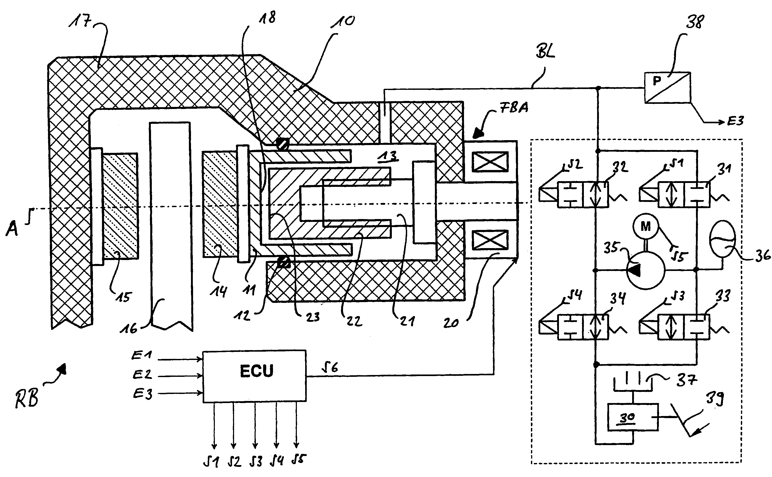
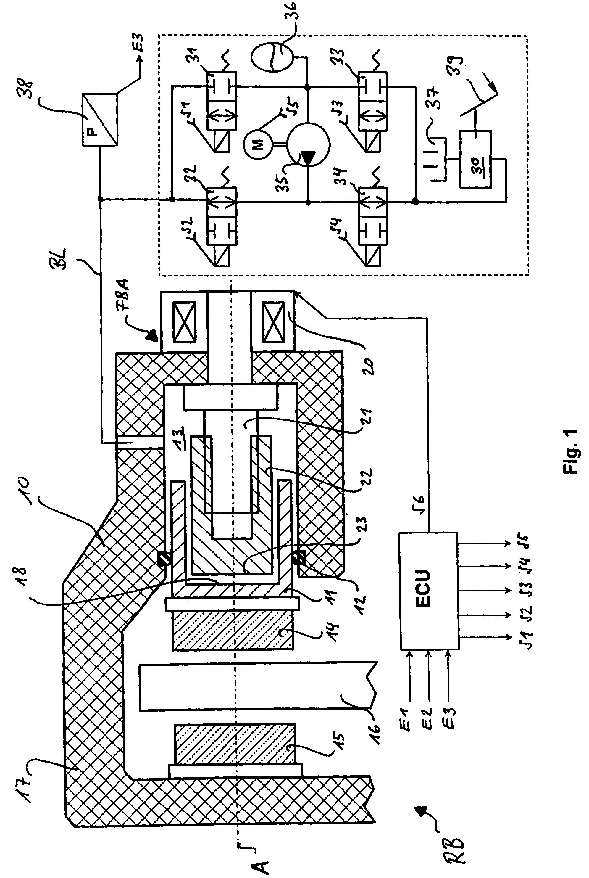
[0027]FIG. 1 shows an exemplary embodiment of a brake arrangement, which can be operated according to the inventive process, for a wheel brake RB. The brake arrangement comprises a service brake arrangement BBA which acts hydraulically on a wheel brake RB by way of a brake line BL. A parking brake system FBA with an electromotive actuating unit is integrated in the wheel brake.

[0028]To control / regulate the service and parking brake system, a common electronic control unit ECU is provided, in which, or in the computer unit of which, the inventive process is preferably implemented as software. A person skilled in the art will understand that the service and parking brake system can also be controlled / regulated starting from separate electronic control units, which exchange data by way of a communications system, e.g. CAN-bus.

[0029]The wheel brake RB illustrated here in a longitudinal section with reference to its longitudinal axis A has a housing 10 in which a brake piston 11 is recei...


PUM


Abstract

A process for operating the brake arrangement of a vehicle is presented, which comprises an electrically controllable service brake system, which is set to generate brake forces independently of driver actuation, andwhich comprises an electrically controllable parking brake system, which is set to generate brake forces and maintain these forces. So that the parking brake system or its electromechanical actuating unit only needs to cope with relatively small load situations, it is proposed that, when, for certain operating conditions, the parking brake system has to maintain brake forces which are greater than the brake forces it is able to generate itself, the service brake system generates the additionally required brake forces.

Description

CROSS-REFERENCE TO RELATED APPLICATIONS[0001]This application is a continuation of International Application No. PCT / EP2005 / 000878 filed Jan. 28, 2005, the disclosures of which are incorporated herein by reference, and which claimed priority to German Patent Application No. DE 10 2004 004 992.0 filed Jan. 30, 2004, the disclosures of which are incorporated herein by reference.BACKGROUND OF THE INVENTION[0002]The invention relates to a process for operating the brake arrangement of a vehicle, which brake arrangement comprises an electrically controllable service brake system, which is set to generate brake forces independently of driver actuation, and which comprises an electrically controllable parking brake system, which is set to generate brake forces and maintain these forces.[0003]The service brake system enables the driver to gradually reduce the speed of the vehicle during its operation or to bring the vehicle to a standstill. Modern vehicles are today equipped with an electri...

Claims


Application Information

Patent Timeline
Patent Type & Authority Patents(United States)
IPC IPC(8): B60T13/10B60T13/66B60T7/10B60T7/12B60T13/74B60T17/16F16D65/14
CPCB60T7/107B60T7/122B60T13/741B60T17/16F16D65/18F16D2127/06F16D2121/02F16D2121/24F16D2123/00B60T2201/06B60T8/32B60T8/4872B60T7/10B60T7/12B60T13/74
Inventor LEITER, RALFPOERTZGEN, GREGOR
Owner LUCAS AUTOMOTIVE GMBH
Why Eureka
Try Eureka