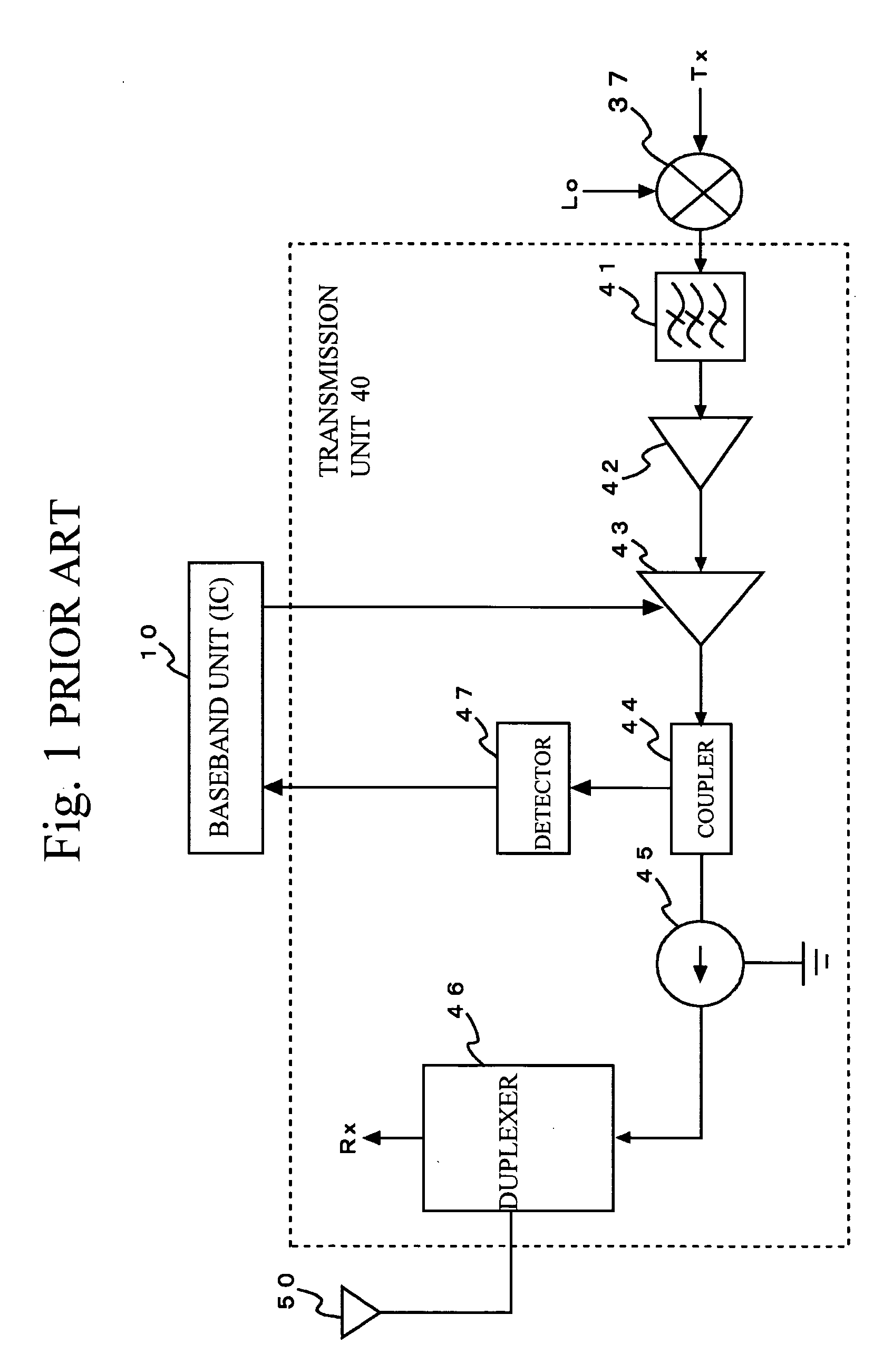
Transmission module

a technology of transceiver and module, which is applied in the direction of antennas, electrically long antennas, electrical equipment, etc., can solve the problems of troublesome work, power consumption in the isolator, and difficulty in achieving impedance matching in the transmitter uni

Inactive Publication Date: 2010-06-29
TAIYO YUDEN KK
View PDF17 Cites 12 Cited by
  • Summary
  • Abstract
  • Description
  • Claims
  • Application Information

AI Technical Summary

Benefits of technology

[0011]The present invention has been made in view of the above circumstances and provides a transmission module in which impedance matching can easily be designed.
[0013]The transmission module may further include: a filter that is arranged in front of the power amplifier and eliminates unnecessary components from the radio frequency signal; a detector detecting part of the radio frequency signal branched into the detector by the coupler; and a duplexer that is provided between the antenna and the coupler and extracts a signal received by the antenna, the filter, the detector and the duplexer being mounted on the substrate.

Problems solved by technology

In addition, power consumption takes place in the isolator 45.
This makes it difficult to achieve impedance matching in the transmitter unit 40 and needs troublesome work.

Method used


Image

  • Transmission module
  • Transmission module
  • Transmission module

Examples


Embodiment Construction

[0028]A description will now be given, with reference to the accompanying drawings, of embodiments of the present invention.

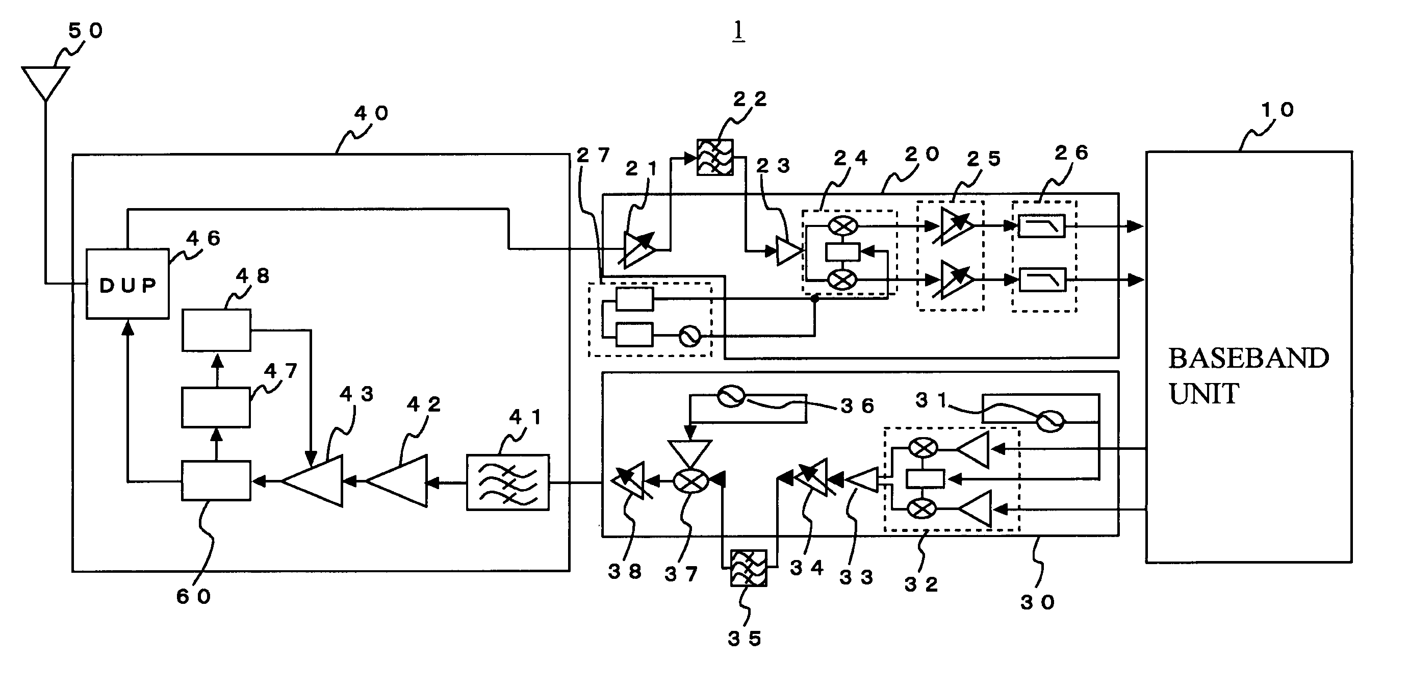
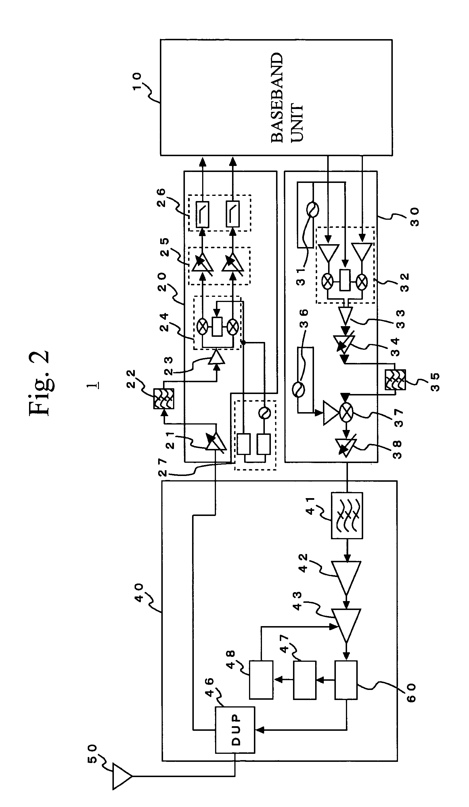
[0029]Referring to FIG. 2, there is illustrated a cellular phone 1 in which a transmission module of the present invention is incorporated. The cellular phone 1 is equipped with the baseband unit 10, a receiver section 20, a transmitter section 30, a radio frequency section (transmission module) 40A, and the antenna 50.

[0030]The baseband unit 10 is an LSI device and mainly has three functions. The first function is baseband signal processing for the baseband transmitted signal to be supplied to the transmitter section 30 and the baseband received signal supplied from the receiver section 20. The second function is control processing such as a communications control and a peripheral circuit control. The third function is voice encoding / decoding.

[0031]The receiver section 20 has a low-noise amplifier (LNA) 21, a bandpass filter (BPF) 22, a splitter 23, a demodula...


PUM


Abstract

A transmission module includes: a power amplifier amplifies power of a radio frequency signal that is to be transmitted via an antenna; a coupler that allows the radio frequency signal from the power amplifier to travel toward the antenna and causes adverse radio frequency power to ground; and a substrate provided with the power amplifier and the coupler.

Description

BACKGROUND OF THE INVENTION[0001]1. Field of the Invention[0002]The present invention generally relates to a transmission module incorporated in a cellular telephone for mobile communications or the like.[0003]2. Description of the Related Art[0004]FIG. 1 shows the configuration of a conventional transmitter unit 40. The transmitter unit 40 amplifies the power of a radio frequency (high frequency) signal on which data are superimposed and outputs the amplified radio frequency signal through an antenna. The transmitter unit 40 has a SAW (Surface Acoustic Wave) filter 41, a driver amplifier 42, a power amplifier 43, a coupler 44, an isolator (circulator) 45, and a duplexer 46, which are connected in this order. The coupler 44 branches a part of the transmitted signal amplified by the power amplifier 43 into a detector 47 so that the transmitted signal is fed back to the power amplifier 43 for output stabilization.[0005]A transmitted signal Tx is mixed with a local oscillation (LO) sig...

Claims


Application Information

Patent Timeline
Patent Type & Authority Patents(United States)
IPC IPC(8): H04B1/02H04B1/04H01Q11/12
CPCH04B1/04H04B2001/0416
Inventor FUKUDA, YASUSHI
Owner TAIYO YUDEN KK
Why Eureka
Try Eureka