Cyclone separator with fine particle separation member

a technology of cyclone separator and contaminant separation, which is applied in the direction of separation process, vortex flow apparatus, cleaning filter means, etc., can solve the problems of not adequately solving the problem of keeping dirt and airflow separated, fine particles cannot pass through the apertured particle separation member into the dead zone, and fine particles are not separated from in the airstream. and eventually trapped in the downstream filter

Active Publication Date: 2010-07-06
BISSELL INC
View PDF17 Cites 49 Cited by
  • Summary
  • Abstract
  • Description
  • Claims
  • Application Information

AI Technical Summary

Benefits of technology

[0033]According to one embodiment of the invention, a vacuum cleaner comprises a cyclone separator assembly comprising a frustoconical separator with inlet at an upper end and an outlet at a lower end and defining a cyclonic airflow chamber for separating contaminants from a dirt-containing airstream and a dirt cup with a sidewall that extends above the lower end of the frustoconical separator. The vacuum cleaner further comprises a nozzle housing including a main suction opening fluidly connected with the inlet of the frustoconical separator and an airstream suction source fluidly connected to the main suction opening and to the cyclonic airflow chamber for transporting dirt-containing air from the main suction opening to the cyclonic airflow chamber, wherein the suction source is adapted to establish and maintain the dirt-containing airstream from the main suction opening to the inlet of the frustoconical separator. A portion of the airstream exiting the frustoconical separator exits through the lower end and enters the dirt cup to create a second rotational airstream in the dirt cup to separate lighter debris contained within the dirt cup and prevent re-entry of the lighter debris into the frustoconical separator.

Problems solved by technology

Separation of the dirt / dust from the air is not difficult, but the problem of keeping the dirt separated from the airflow has not been adequately solved.
However, as larger particles of dirt collect on top of the separation member, the fine particles cannot pass through the apertured particle separation member into the dead zone.
As a result, the fine particles are not separated from in the airstream and are eventually trapped in a downstream filter.
However, this separator plate has a problem similar to that found in the Conrad 197 patent; as large particles of dirt collect on the particle-separating plate, the larger particles block the path of the fine particles, with the result that a significant amount of fine particles cannot pass through the separator plate and remains in the cyclonic air flow.

Method used


Image

  • Cyclone separator with fine particle separation member
  • Cyclone separator with fine particle separation member
  • Cyclone separator with fine particle separation member

Examples


Embodiment Construction

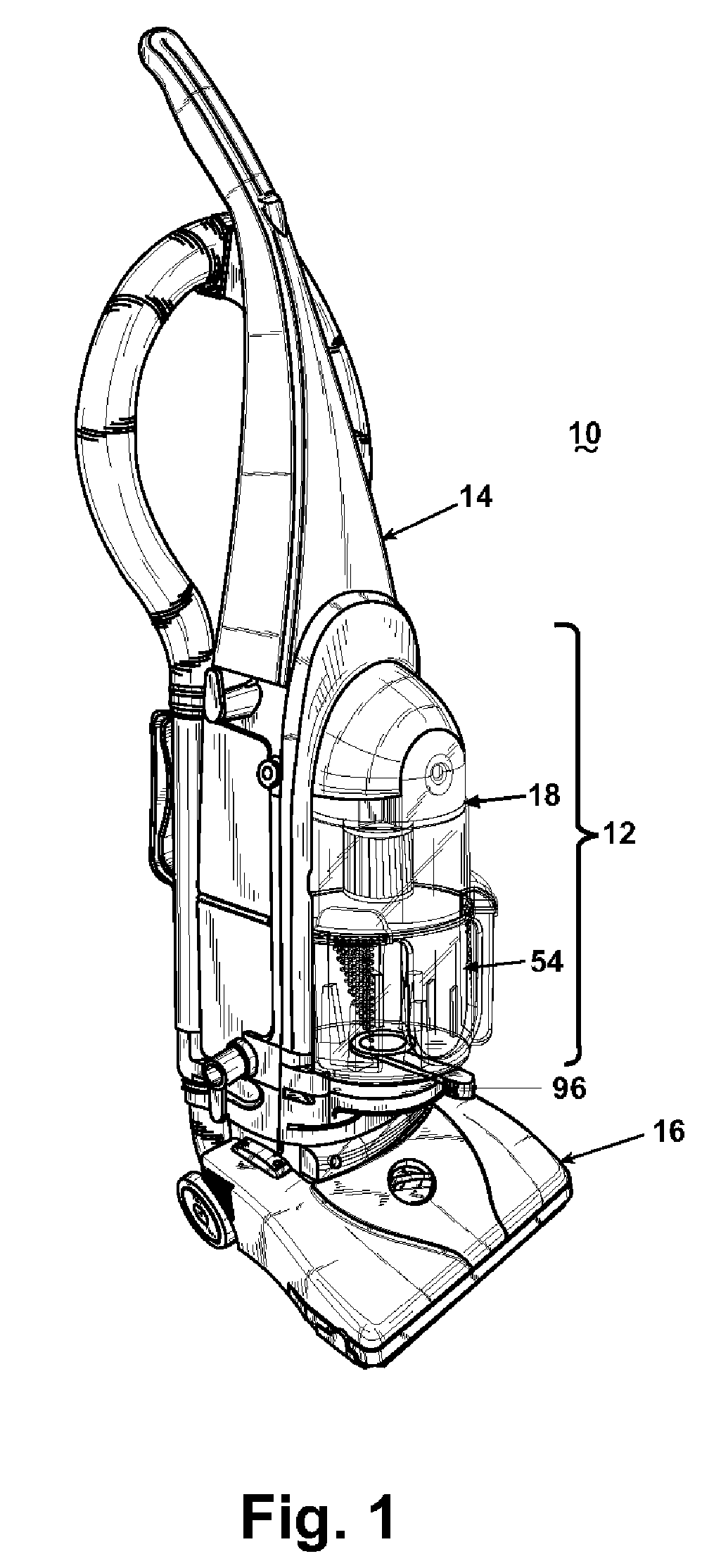
[0055]An upright vacuum cleaner 10 with a cyclone separator assembly 12 according to one embodiment of the invention is shown in FIG. 1. The cyclone separator assembly 12 is mounted to an upright handle 14 pivotally mounted to a nozzle base housing 16 having a main suction opening adjacent the surface to be cleaned.

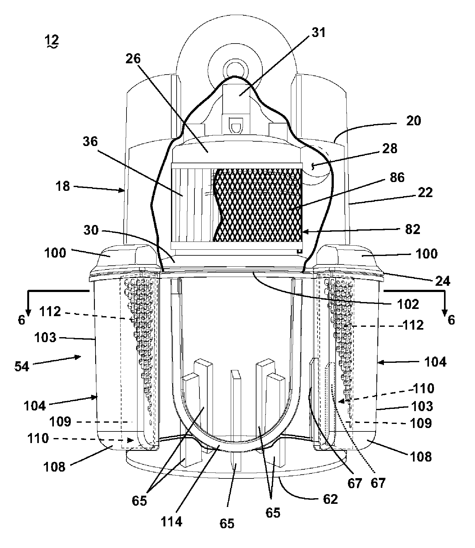
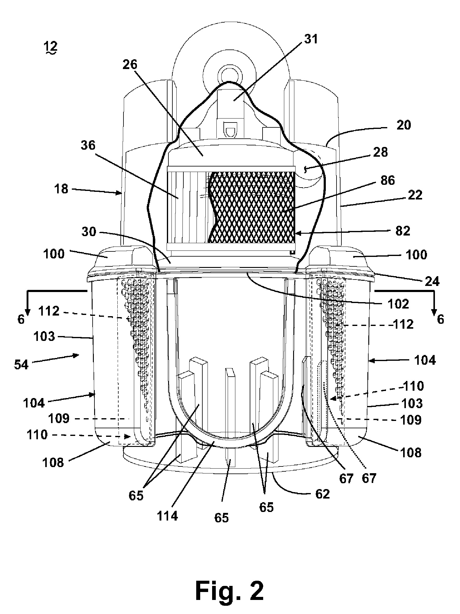
[0056]Referring to FIGS. 2-4, the cyclone separator assembly 12 according to the invention comprises a cylindrical cyclone separator 18 and a dirt cup 54 located below the cyclone separator 18. The cyclone separator 18 has a top wall 20 and a generally orthogonal, cylindrical sidewall 22 that terminates in a lower offset lip 24. An annular collar 26 depends from the top wall 20 and is centered in the cylindrical cyclone separator 18. An exhaust outlet 31 that extends through the top wall 20 in alignment with a central longitudinal axis of the annular collar 26 is fluidly connected with a suction source 40, such as a motor and fan assembly. The sidewall 22 further includes...


PUM

PropertyMeasurementUnit
surface areaaaaaaaaaaa
speedaaaaaaaaaa
centrifugal forceaaaaaaaaaa

Abstract

A cyclone separator assembly comprises a cyclone separator that removes large particles of dirt from a working airstream as it flows through the cyclone separator, and the separated large particles of dirt are deposited into a dirt cup. The cyclone separator assembly further includes a fine particle separation member comprising a plurality of apertures for separating fine particles of dirt from air in the cyclone separator or the dirt cup.

Description

CROSS REFERENCE TO RELATED APPLICATION[0001]This application claims the benefit of U.S. Provisional Application Ser. No. 60 / 522,213, filed on Sep. 1, 2004.FIELD OF THE INVENTION[0002]The invention relates to vacuum cleaners, and in particular to a cyclone separator for a vacuum cleaner. In one of its aspects, the invention relates to a vacuum cleaner with a fine contaminant separation member for removing fine contaminants from air. In another of its aspects, the invention relates to a particle separator a particle collector connected to a cyclonic airflow chamber and / or a dirt cup through a fine contaminant separation member.DESCRIPTION OF THE RELATED ART[0003]Cyclone separators are well known. Some follow the textbook examples using frustoconical shaped separators and others use high-speed rotational motion of the dir-laden air to separate the dirt by centrifugal force. Separation of the dirt / dust from the air is not difficult, but the problem of keeping the dirt separated from the...

Claims


Application Information

Patent Timeline
Patent Type & Authority Patents(United States)
IPC IPC(8): A47L9/16A47L5/36B01D45/16B01D50/00B04C5/187B04C9/00
CPCA47L5/362A47L9/1608A47L9/1666A47L9/1683B01D45/16B01D50/002B04C5/187B04C9/00B04C2009/004B01D50/20B01D50/00
Inventor MCDOWELL, DAVID E.MOYHER, JR., GEORGEREED, JR., CHARLES A.PARKER, TIMOTHY S.
Owner BISSELL INC
Why Eureka
Try Eureka