Spraying device and use of this device

a technology of sprayed fluid and droplets, which is applied in the direction of single-unit apparatus, lighting and heating apparatus, combustion types, etc., can solve the problems of bringing about a large dispersion of the diameter of the droplets of the sprayed fluid product, difficult control, and undesirable dispersion, so as to improve the control of the distribution of droplets

Active Publication Date: 2010-07-06
ALBEA LE TREPORT
View PDF10 Cites 21 Cited by
  • Summary
  • Abstract
  • Description
  • Claims
  • Application Information

AI Technical Summary

Benefits of technology

[0016]By virtue of the arrangements described above, the size of the droplets sprayed by the spraying device are controlled and good uniformity of this size of the droplets is ensured.
[0018]In addition, the invention aims to improve control over the shape of the aerosol obtained leaving the spray nozzle while enabling the calibrated holes to be made simply.
[0020]Thus, in the rest state, the holes can be made in a simple manner in the flat front wall, it being possible for each hole to have an axis that extends in a plane parallel to a central axis perpendicular to the front wall. In the actuating state, when the fluid product is sprayed, the axes of the holes move way from the central axis so as to have an outwards divergence and the fluid product can be sprayed in the form of an aerosol having a high cone angle.
[0037]In addition, the invention aims to improve control over the distribution of droplets and the form of the aerosol.

Problems solved by technology

In spraying devices of this type, the spray nozzles, which are conventionally mounted on pumps or on spray valves, have the disadvantage of bringing about a large dispersion of the diameter of the droplets of the sprayed fluid product.
Indeed, in spray nozzles of a device of this type, the fluid product is split up into fine droplets by a dynamic phenomenon that is particularly difficult to control, generally consisting of creating a vortex inside the inner chamber of the nozzle and of splitting up the fluid product into fine droplets as it leaves at a very high velocity through the central hole.
This dispersion can prove to be undesirable when it is desired to spray droplets with substantially uniform sizes.
Moreover, droplets with very different sizes also follow very different trajectories, which is harm for the controlled application of the sprayed product.
For example, when spraying a perfume onto the skin of a user, droplets that are too large can fall on the clothes of the user instead of being projected onto the skin, with the risk of producing indelible spots.

Method used


Image

  • Spraying device and use of this device
  • Spraying device and use of this device
  • Spraying device and use of this device

Examples


second embodiment

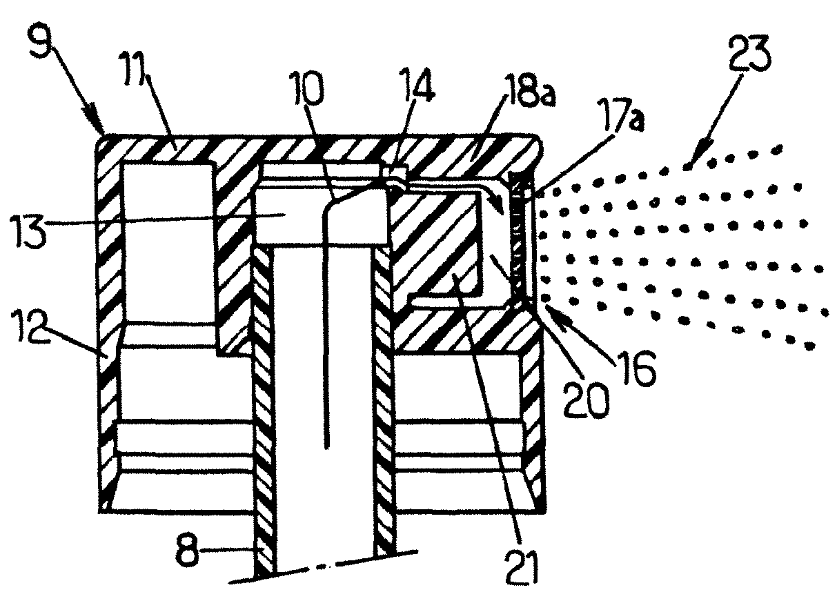
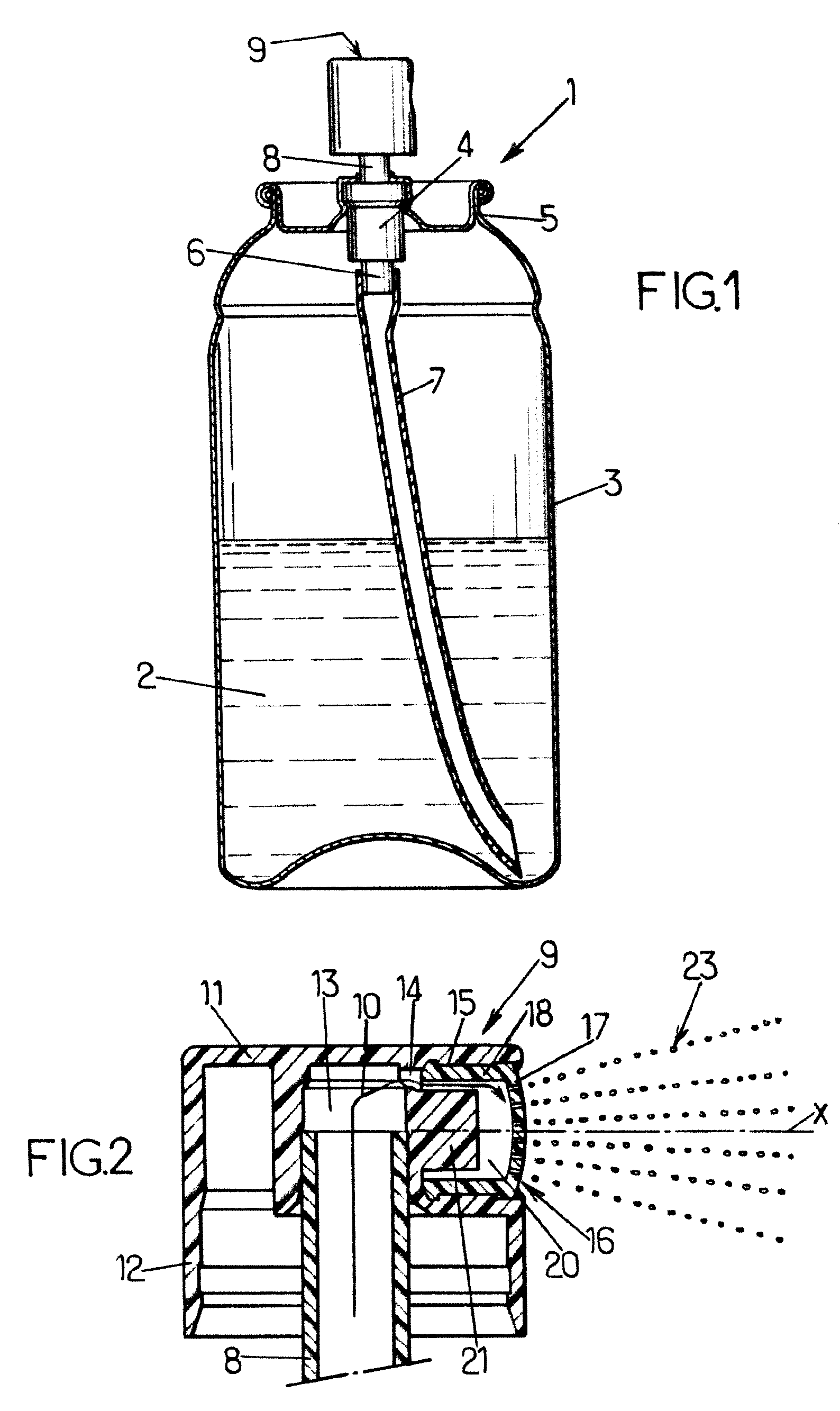
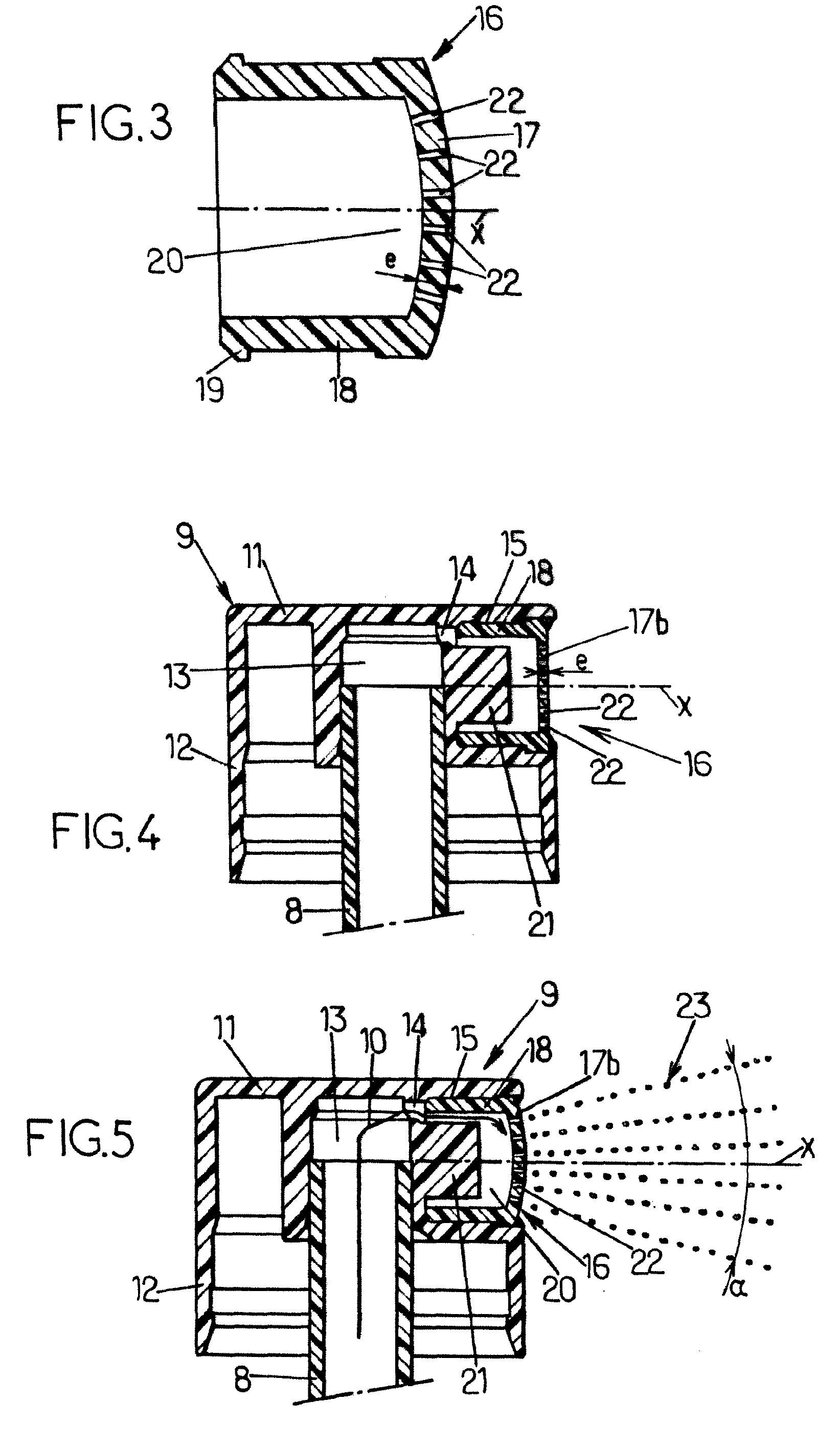
[0105]In the second embodiment shown in FIGS. 4 and 5, the spray nozzle 16 differs from the spray nozzle previously described in that the front wall 17b is elastically deformable between a rest state shown in FIG. 4 and an actuating state shown in FIG. 5, when the fluid product under pressure is transferred into the inner chamber 20.

[0106]In particular, in the rest state, the front wall 17b extends in a plane perpendicular to the central axis X. Also, in the actuating state, the front wall 17b has an outwardly directed convexity so that, for example, it has the form of a spherical cap.

[0107]As shown in FIGS. 4 and 5, in the rest state, the front wall 17b is flat. This arrangement makes it possible to produce the holes 22 in a simple manner having an axis that extends, for example, along a normal to the front wall 17b, parallel to the central axis X. When a user presses the push-button 9, the fluid product under pressure is transferred into the inner chamber 20, exerting a force on t...

third embodiment

[0112]FIGS. 8 and 9 is similar to the embodiment of FIGS. 2 and 3 and will therefore not be described once again in detail. In this embodiment of FIGS. 8 and 9, the spray nozzle 16 differs from the spray nozzle previously described by the fact that the front wall 17a is made of a material different from the front wall 18 of the nozzle, the side wall 18 being a part distinct from the push-button 9, secured to the push-button 9.

[0113]In a variant shown in FIG. 10, it is possible to provide for the front wall 17a to be secured to the side wall 18a formed in a single piece with the push-button 9.

[0114]For example, the front wall 17a can be made of a material chosen from silicon, glass, metals and their alloys, ceramics or polymers, while the side wall 18 is made of a plastic as in the previous example, it being possible that said side wall 18 to be overmoulded over the periphery of the front wall 17a.

[0115]In the embodiment of FIGS. 8 and 9, the front wall 17a is flat, but could be bow...

fourth embodiment

[0122]In the invention, shown in FIGS. 11 to 13, complementary to or independent of the embodiment of the elastically deformable front wall 17, each hole 22 of the front wall 17 of the spray nozzle extends along an axis X2 inclined with respect to the normal X1 to said front wall in the region of said hole 22. The axis X2 and the normal X1 define a plane substantially tangential to a circle C centred on the central point of the front wall 17 and passing by the hole 22. The axes X2 of all the holes 22 have an inclination γ in the same direction with respect to the corresponding normal X1. This inclination can advantageously be the same for all the holes, and is for instance between 10 and 60°, in particular of the order of 30°.

[0123]On account of the fact that the holes 22 are all inclined in the same angular direction 24 (FIG. 6), when an aerosol A is generated by the spray nozzle (see FIG. 8), the trajectory v followed by each droplet of the aerosol liquid is a swirling trajectory ...


PUM


Abstract

Manual spraying device including a push-button that can be actuated manually, the push-button including a spray nozzle, the spray nozzle having an inner chamber adapted to receive a non-gaseous fluid product under pressure and delimited towards the outside by a perforated front wall, a reservoir for the fluid product to be sprayed, and a dispensing device that can be mechanically actuated by the push-button and adapted to transfer the fluid product from the reservoir to the inner chamber of the nozzle, the front wall having a plurality of calibrated holes, each having a diameter of between 1 and 100 μm, the diameter of each hole not differing from a mean of the diameters of the various holes by more than 20%.

Description

CROSS-REFERENCE TO RELATED APPLICATIONS[0001]The present application claims priority of French patent application No. 06 06259 filed on Jul. 10, 2006 and of French patent application No. 07 00485 filed on Jan. 24, 2007, the content of which is incorporated herein by reference.FIELD OF THE INVENTION[0002]The present invention relates to a spraying device and a use for this device.BACKGROUND OF THE INVENTION[0003]More particularly, the invention relates to a manual spraying device comprising:[0004]a push-button that can be actuated manually, said push-button comprising a spray nozzle, said spray nozzle having an inner chamber adapted to receive a non-gaseous fluid product under pressure and delimited towards the outside by a perforated front wall,[0005]a reservoir for the fluid product to be sprayed,[0006]and a dispensing device that can be mechanically actuated by the push-button and adapted to transfer the fluid product from the reservoir to the inner chamber of the nozzle.[0007]Doc...

Claims


Application Information

Patent Timeline
Patent Type & Authority Patents(United States)
IPC IPC(8): B05B7/32B05B1/14B05B1/00
CPCB05B1/14B05B1/185B05B11/30B65D83/14B65D83/753B05B11/10
Inventor CLERGET, BERNARDSONGBE, JEAN-PIERREDUMONT, PIERRE
Owner ALBEA LE TREPORT
Why Eureka
Try Eureka