
Sleeve assembly for spinal stabilization system and methods of use

a spinal stabilization system and spinal cord technology, applied in the field of minimally invasive spinal stabilization systems, can solve the problems of destabilizing bone and affecting surrounding structures, pain and/or nerve damage, and altering the natural spacing between adjacent vertebra

Active Publication Date: 2010-07-06
INNOVATIVE SPINE LLC
View PDF12 Cites 70 Cited by
  • Summary
  • Abstract
  • Description
  • Claims
  • Application Information

AI Technical Summary

Benefits of technology

"The present invention is a new tool for use in minimally invasive spinal stabilization surgery. The invention includes an outer sleeve assembly that prevents the screw from becoming detached from the inner sleeve during surgery. The outer sleeve slides over the inner sleeve and is locked in place, ensuring proper alignment for receiving a stabilization rod. The invention also includes a method for easily installing and removing the outer sleeve assembly. The use of this tool simplifies the surgical procedure and reduces the risk of complications."

Problems solved by technology

Degeneration may destabilize bone and affect surrounding structures.
For example, destabilization of a spine may result in alteration of a natural spacing between adjacent vertebrae.
Pressure applied to the nerves may cause pain and / or nerve damage.
Conventional procedures may result in trauma to the soft tissue, for example, due to muscle stripping.
Dissection and retraction of soft tissue may cause trauma to the soft tissue, and extend recovery time.
Minimally invasive procedures and systems may reduce recovery time as well as trauma to the soft tissue surrounding a stabilization site.
The Landry device and its use are cumbersome in that Landry requires a separate screw in the sleeve as well as a separate driver for engaging and disengaging this screw.
The smaller securing screws used in the Landry device are delicate and prone to breakage.
Retrieval of broken securing screws is both time consuming and potentially injurious to the patient.

Method used


Image

  • Sleeve assembly for spinal stabilization system and methods of use
  • Sleeve assembly for spinal stabilization system and methods of use
  • Sleeve assembly for spinal stabilization system and methods of use

Examples


Embodiment Construction

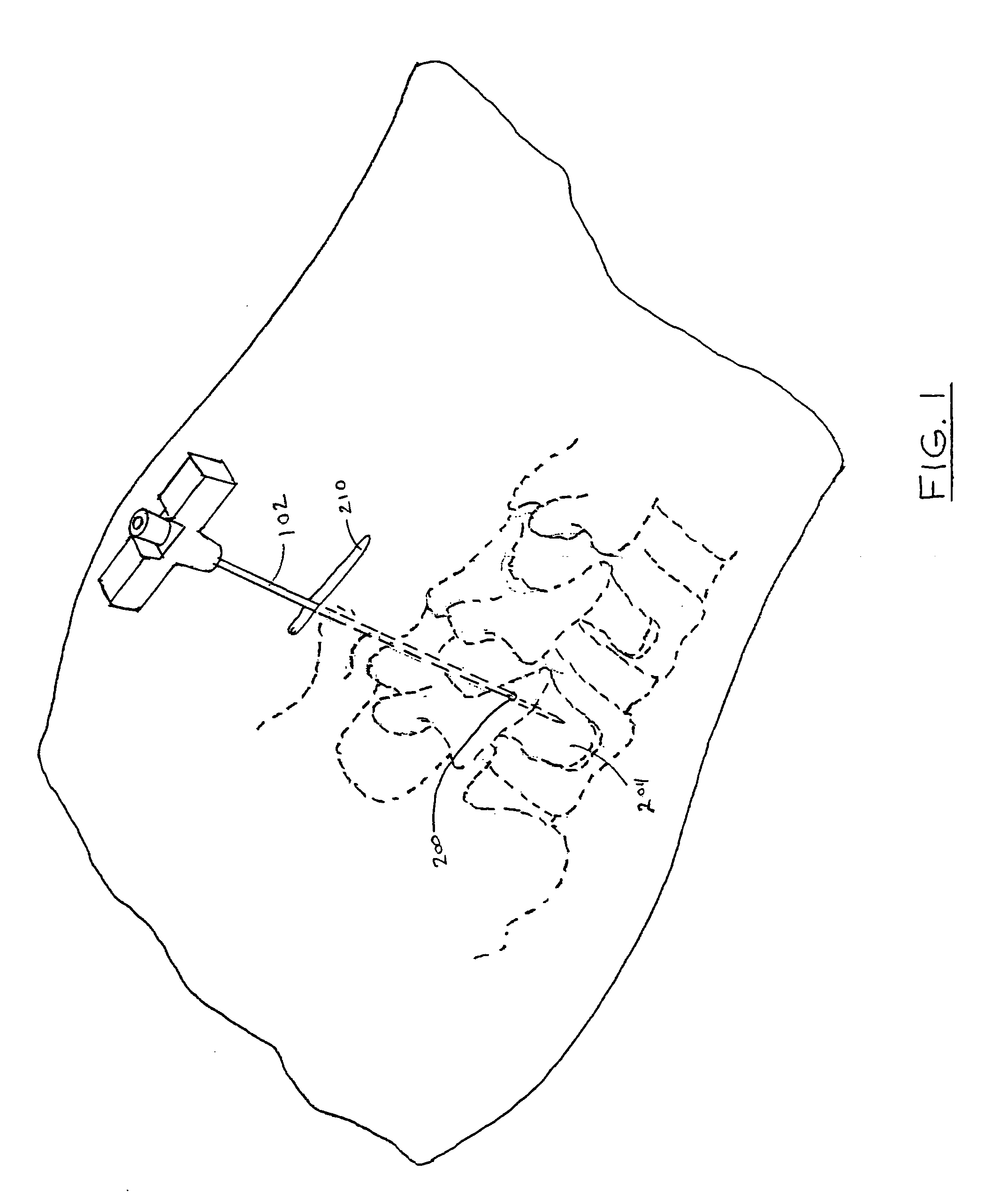
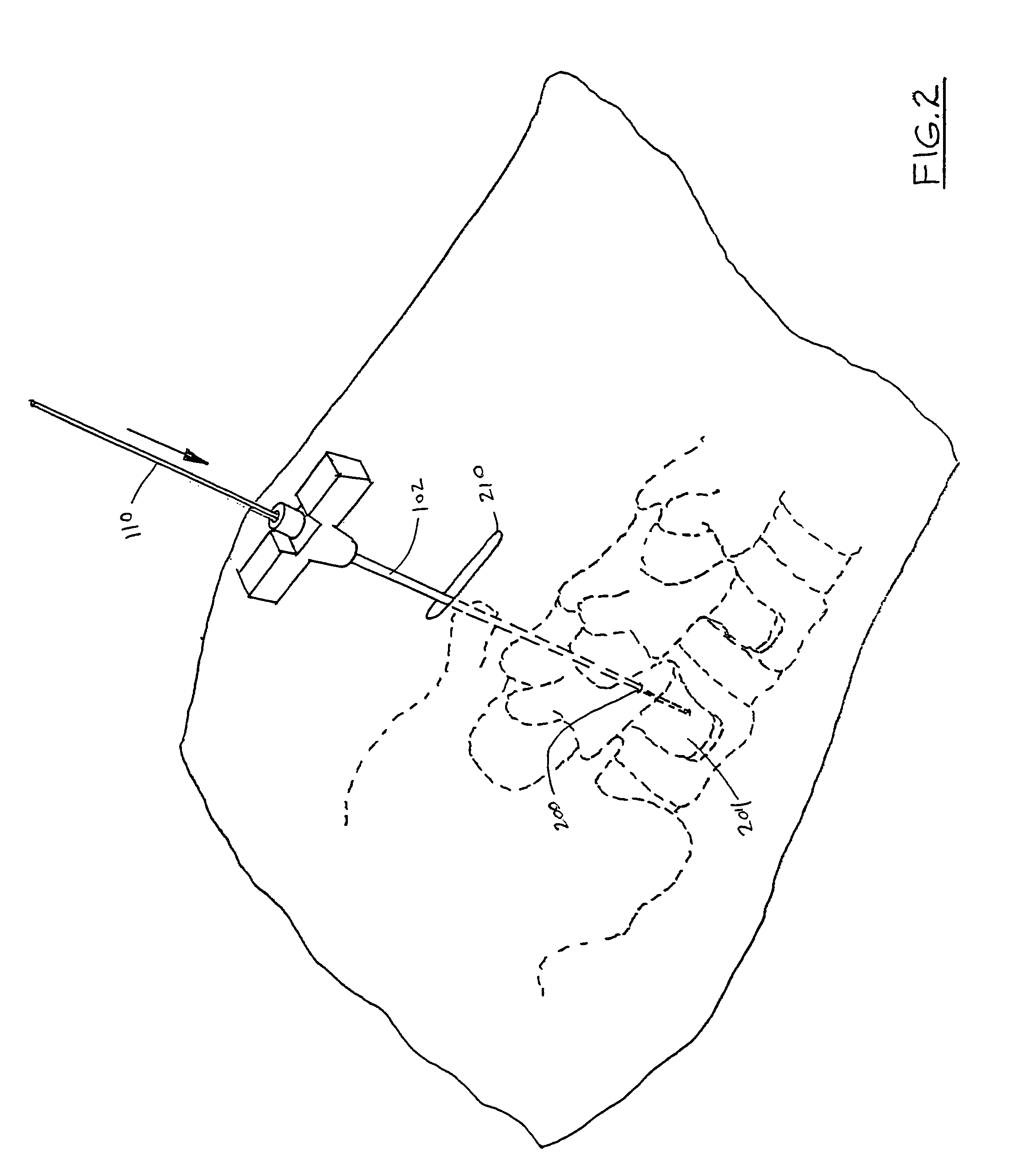
[0051]Spinal stabilization systems are installed in a patient to stabilize a portion of a spine. Spinal stabilization may be used, but is not limited to use, in patients having degenerative disc disease, spinal stenosis, spondylolisthesis, pseudoarthrosis, and / or spinal deformities; in patients having fracture or other vertebral trauma; and in patients after tumor resection. More and more frequently, spinal stabilization systems are installed using a minimally invasive procedure. A special instrumentation set is used for such procedures which include surgical instruments as well as the components used to form the spinal stabilization system in the patient.

[0052]Spinal stabilization systems are frequently used to achieve rigid pedicle fixation while minimizing the amount of damage to surrounding tissue. In some embodiments, a spinal stabilization system may be used to provide stability to two adjacent vertebrae (i.e., one vertebral level), and may include two bone screw assemblies. I...


PUM


Abstract

The present invention is a one or two-part sleeve assembly for use during minimally invasive spinal stabilization surgery. An outer sleeve is designed to slide over the coupling between a polyaxial screw and an inner sleeve so as to prevent the screw from becoming disengaged from the inner sleeve during surgery. The outer sleeve includes a lower generally cylindrical wall having a slot, and an upper extension having an outwardly protruding manipulation handle attached to it. The slot in the lower section extends the entire length of the cylindrical wall, giving it a generally “C” shaped cross section. This slot corresponds with a similar slot on the inner sleeve for receiving a stabilizing rod to be attached to the polyaxial screw during surgery. The interior diameter of the lower section is approximately the same as the outer diameter of the inner sleeve, so that the outer sleeve may slide snugly over the inner sleeve and the screw coupling. In addition, the edges of the cylindrical wall adjacent to the longitudinal slot are flattened so as to conform to the shape of the inner sleeve and the head portion of the polyaxial screw where it couples with the inner sleeve.

Description

[0001]This application claims the benefit of U.S. Provisional Application No. 60 / 688,859, filed on Jun. 8, 2005, which is incorporated herein by this reference.BACKGROUND OF THE INVENTION[0002]1. Field of the Invention[0003]The present invention relates to minimally invasive spinal stabilization systems, more particularly to a new and improved inner and outer sleeve assembly used to simplify and expedite minimally invasive spinal stabilization surgery.[0004]2. Description of the Prior Art[0005]Bone may be subject to degeneration caused by trauma, disease, and / or aging. Degeneration may destabilize bone and affect surrounding structures. For example, destabilization of a spine may result in alteration of a natural spacing between adjacent vertebrae. Alteration of a natural spacing between adjacent vertebrae may subject nerves that pass between vertebral bodies to pressure. Pressure applied to the nerves may cause pain and / or nerve damage. Maintaining the natural spacing between verte...

Claims


Application Information

Patent Timeline
Patent Type & Authority Patents(United States)
IPC IPC(8): A61B17/58A61B17/60A61F2/00
CPCA61B17/7085A61B17/7037A61B2019/461A61B2090/061Y10S606/916
Inventor FARR, MORTEZA M.KEANE, CIARAN
Owner INNOVATIVE SPINE LLC
Learn More