
Voltage-pulse converting circuit and charge control system

a voltage-pulse converting circuit and charge control technology, applied in pulse manipulation, pulse technique, instruments, etc., can solve the problems of increasing the chip size of the integrated circuit, the difficulty of determining whether the input voltage is a positive or negative voltage, and the cost increase, so as to reduce the configuration of the circuit and save power consumption

Inactive Publication Date: 2010-07-06
RENESAS ELECTRONICS CORP
View PDF6 Cites 15 Cited by
  • Summary
  • Abstract
  • Description
  • Claims
  • Application Information

AI Technical Summary

Benefits of technology

The present invention provides a voltage-pulse converting circuit and a charge control system that can downsize and save power consumption. The circuit includes an integrator and input switching unit that switch between different input terminals based on a comparison result of two comparators. This allows for a change in the output voltage curve based on charging or discharging operations, resulting in a pulse that can control the charging of a battery. The charge control system includes the voltage-pulse converting circuit and a control unit that uses the count value of the pulse to control the charging of the battery.

Problems solved by technology

Incidentally, it is difficult to determine whether the input voltage is a positive or negative voltage only by configuring the V-F converter.
This results in a problem in that a chip size of an integrated circuit increases, and a cost increases.
In addition, each time the charge pulses CHG and DSG are output from the comparators 228 and 230, charges should be supplied / pumped to / from the node 240 through the charge / discharge of the capacitor Cp1 or Cp2 of the charging pump 238, which leads to a problem that current consumption increases.

Method used


Image

  • Voltage-pulse converting circuit and charge control system
  • Voltage-pulse converting circuit and charge control system
  • Voltage-pulse converting circuit and charge control system

Examples


first embodiment

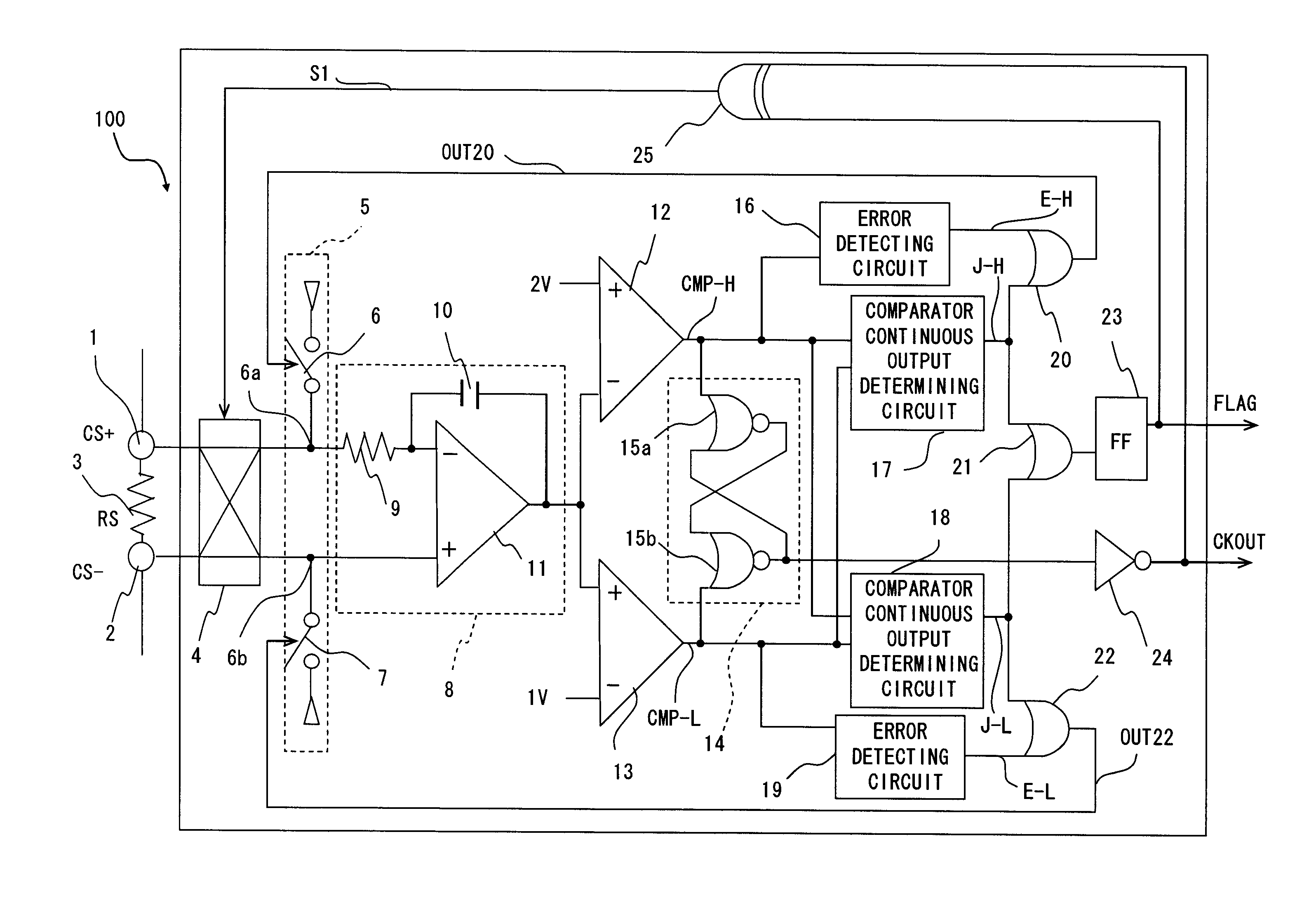
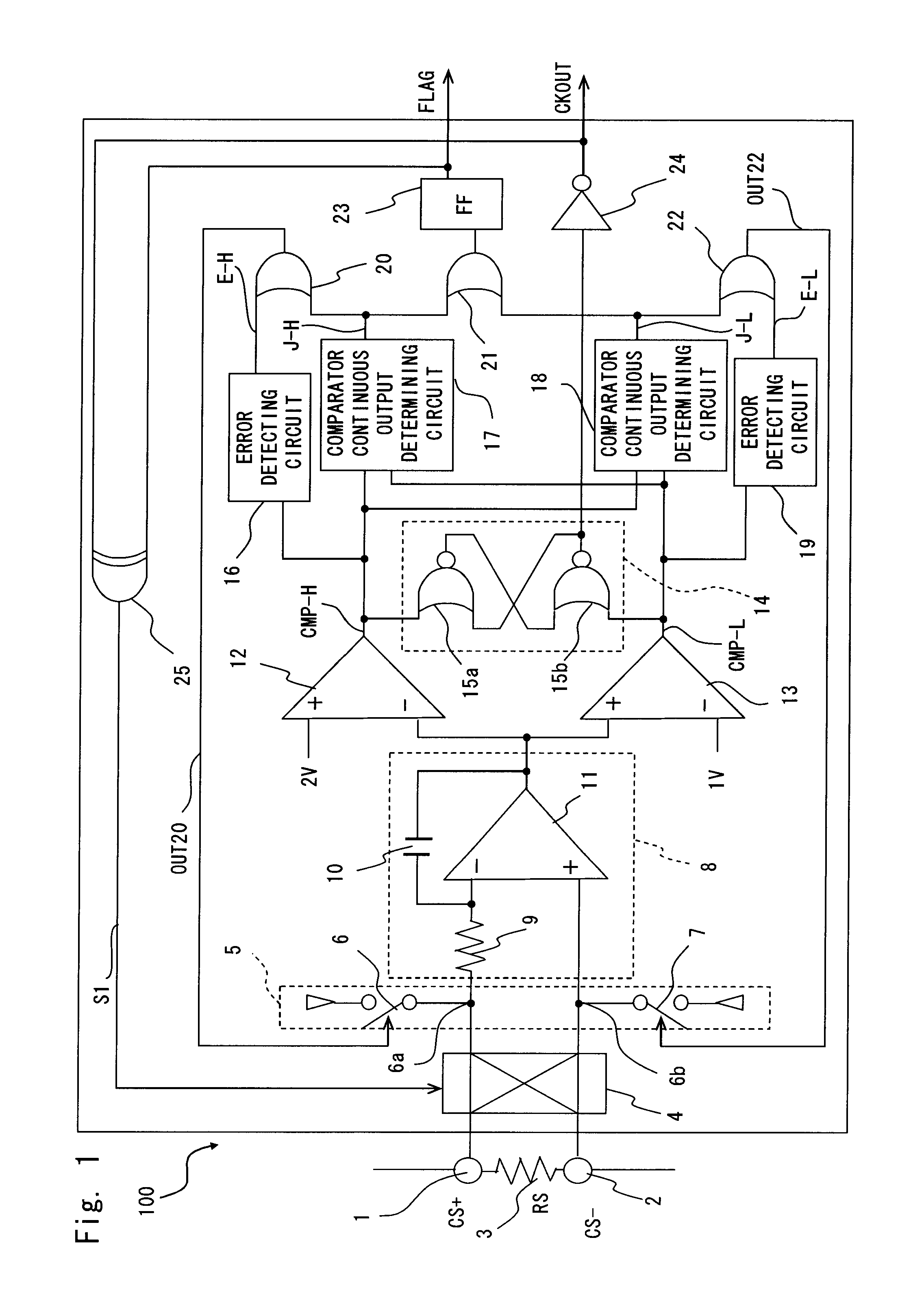
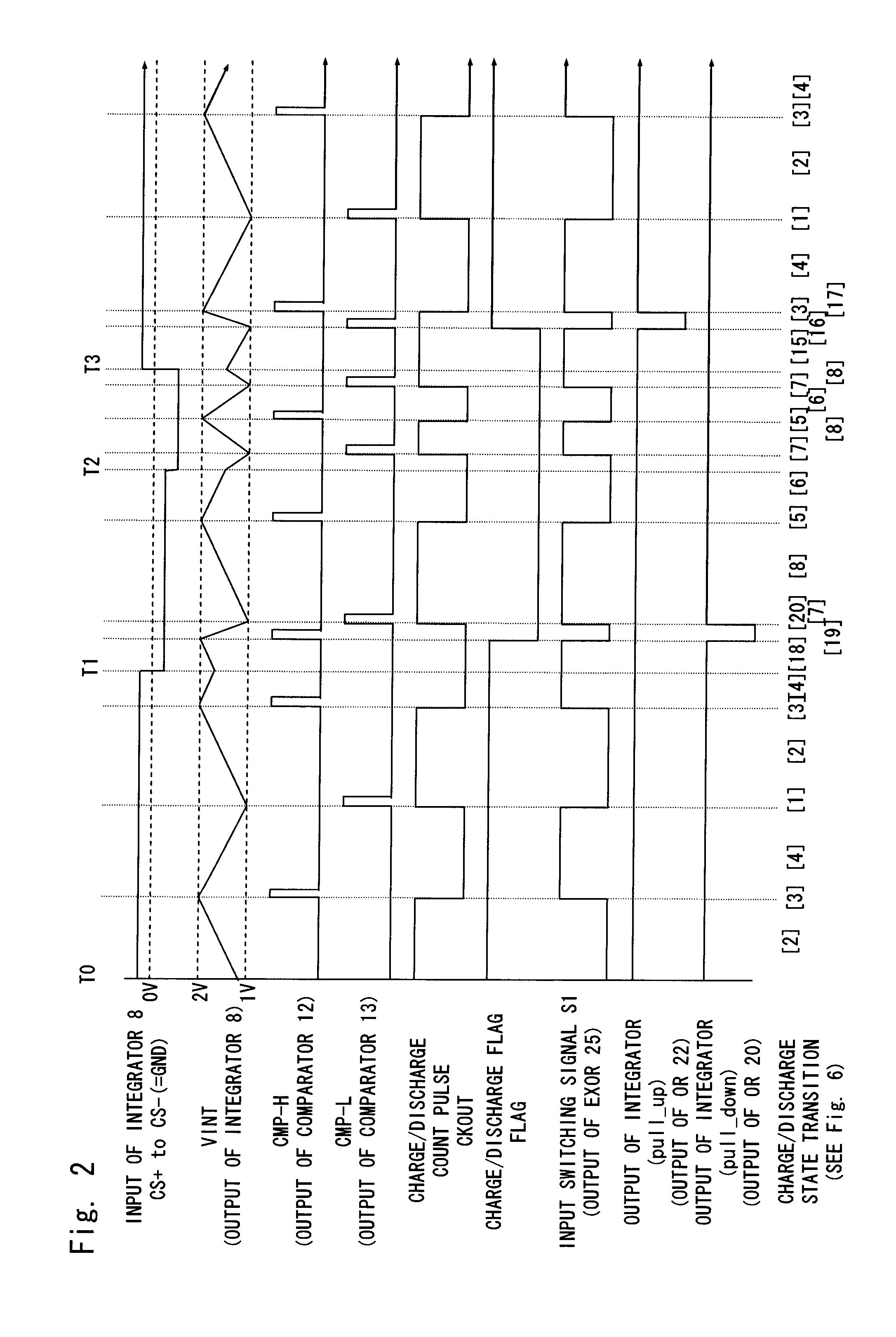
[0034]FIG. 1 is a block diagram of a voltage-pulse converting circuit according to a first embodiment of the present invention, and FIGS. 2 and 3 show an operational waveform example thereof. FIG. 4 illustrates state transition of a voltage-pulse converting circuit 100 of this embodiment.

[0035]As shown in FIG. 1, the voltage-pulse converting circuit 100 includes an input switching circuit 4, an integrator output inductive unit 5 as a voltage inductive unit, an integrator 8, first and second comparators 12 and 13 (window comparator), an RS latch circuit 14, first and second integrator output error detecting circuits 16 and 19, first and second comparator continuous output determining circuits 17 and 18, and a flip-flop FF 23 as a flag output unit.

[0036]The input switching circuit 4 is connected between one terminal (CS positive terminal) 1 and the other terminal (CS negative terminal) 3 of a current sensing resistor (RS) 3, and two input terminals of an integrator 8. A current sensin...

second embodiment

[0069]Next, a voltage-pulse converting circuit according to a second embodiment of the present invention is described. FIG. 5 is a block diagram of the voltage-pulse converting circuit of this embodiment. Incidentally, in this embodiment as shown in FIG. 5, the same components as those of the first embodiment as shown in FIG. 1 are denoted by like reference numerals, and detailed description thereof is omitted.

[0070]As shown in FIG. 5, a voltage-pulse converting circuit 130 of this embodiment differs from the first embodiment in terms of a connection position of the output inductive unit of the integrator. That is, in the first embodiment, the integrator output inductive unit 5 is connected between the input switching circuit 4 and two input terminals of the integrator 8. In this embodiment, the unit is directly connected with an output terminal of the integrator 8.

[0071]In an integrator output inductive unit 35, a switch 36 turned ON / OFF based on the output OUT20 of the OR circuit ...


PUM


Abstract

A voltage-pulse converting circuit according to an embodiment of the invention includes: a first input terminal and a second input terminal applied with an input voltage to be converted into a pulse; an integrator having positive and negative input terminals; an input switching unit switching connection between the first and second input terminal and the positive and negative input terminals of the integrator; and a first comparator comparing a first detection voltage with an output voltage of the integrator and a second comparator comparing a second detection voltage different from the first detection voltage with the output voltage, the input switching unit switching the connection based on a comparison result of the first and second comparators.

Description

BACKGROUND OF THE INVENTION[0001]1. Field of the Invention[0002]The present invention relates to a voltage-pulse converting circuit that converts a voltage into a pulse signal by use of an integrator, and a charge control system incorporating the same.[0003]2. Description of Related Art[0004]Secondary batteries (batteries) such as a lithium cell have been used in a digital camera, a notebook PC, or the like. In this case, it is necessary to accurately control a battery power for the purpose of increasing a battery-based usable life as long as possible. To that end, a charge control system controlling the battery power has been generally provided together with a battery. In such charge control system, for example, a charger is connected between both ends of a battery charger completed by connecting plural secondary batteries in series. A current detecting resistor (sensing resistor) detecting charging / discharging current is connected to one terminal of the battery charger, and this s...

Claims


Application Information

Patent Timeline
Patent Type & Authority Patents(United States)
IPC IPC(8): G05F1/40G05F1/44
CPCH03K3/0231H03K7/06H02J7/0052H02J7/042H02J7/007H02J7/04H02J7/00
Inventor YOKOSAWA, KOUJI
Owner RENESAS ELECTRONICS CORP
Learn More