Hollow core fiber optical gyro

a fiber optic gyro and optical fiber technology, applied in the field of rotating sensors for use in gyro systems, can solve the problems of inaccurate measurement of rotation rate, affecting the accuracy or sensitivity of fog, and affecting the accuracy of fog. or sensitivity,

Active Publication Date: 2010-07-06
HONEYWELL INT INC
View PDF17 Cites 31 Cited by
  • Summary
  • Abstract
  • Description
  • Claims
  • Application Information

AI Technical Summary

Problems solved by technology

In general, the size of the FOG affects the accuracy or sensitivity of a FOG.
For example, smaller FOGs typically have less accuracy than larger FOGs.
In the RFOG, effects stemming from the presence of glass material of the optical fiber may shift the resonance frequencies of the CW and CCW paths and thus produce a false indication of rotation or inaccurate measurement of rotation rate.
A reflective mirror may be used to recirculate the counter-propagating light beams in the coil but this typically reduces the signal-to-noise ratio from losses generated at the transition from the mirror to the coil.
Anomalies that decrease the accuracy of the measurement of the rotational rate may be generated from a non-linear Kerr effect, stimulated Brillioun scattering, polarization errors, bend losses.
These error mechanisms are also sensitive to the environment which, for example, gives rise to unwanted temperature sensitivity.
Polarization-induced errors may result from fiber couplers that incidentally couples light into a second polarization mode, either from one optical fiber to an adjacent optical fiber or within the same fiber.
Polarization-induced error may severely limit the accuracy of the RFOG because determination of the resonance centers for each of the resonance frequencies of the CW and CCW beams directly affects the rotational rate measurement.

Method used


Image

  • Hollow core fiber optical gyro
  • Hollow core fiber optical gyro

Examples


Embodiment Construction

[0015]The following detailed description of the invention is merely exemplary in nature and is not intended to limit the invention or the application and uses of the invention. Furthermore, there is no intention to be bound by any theory presented in the preceding background of the invention or the following detailed description of the invention.

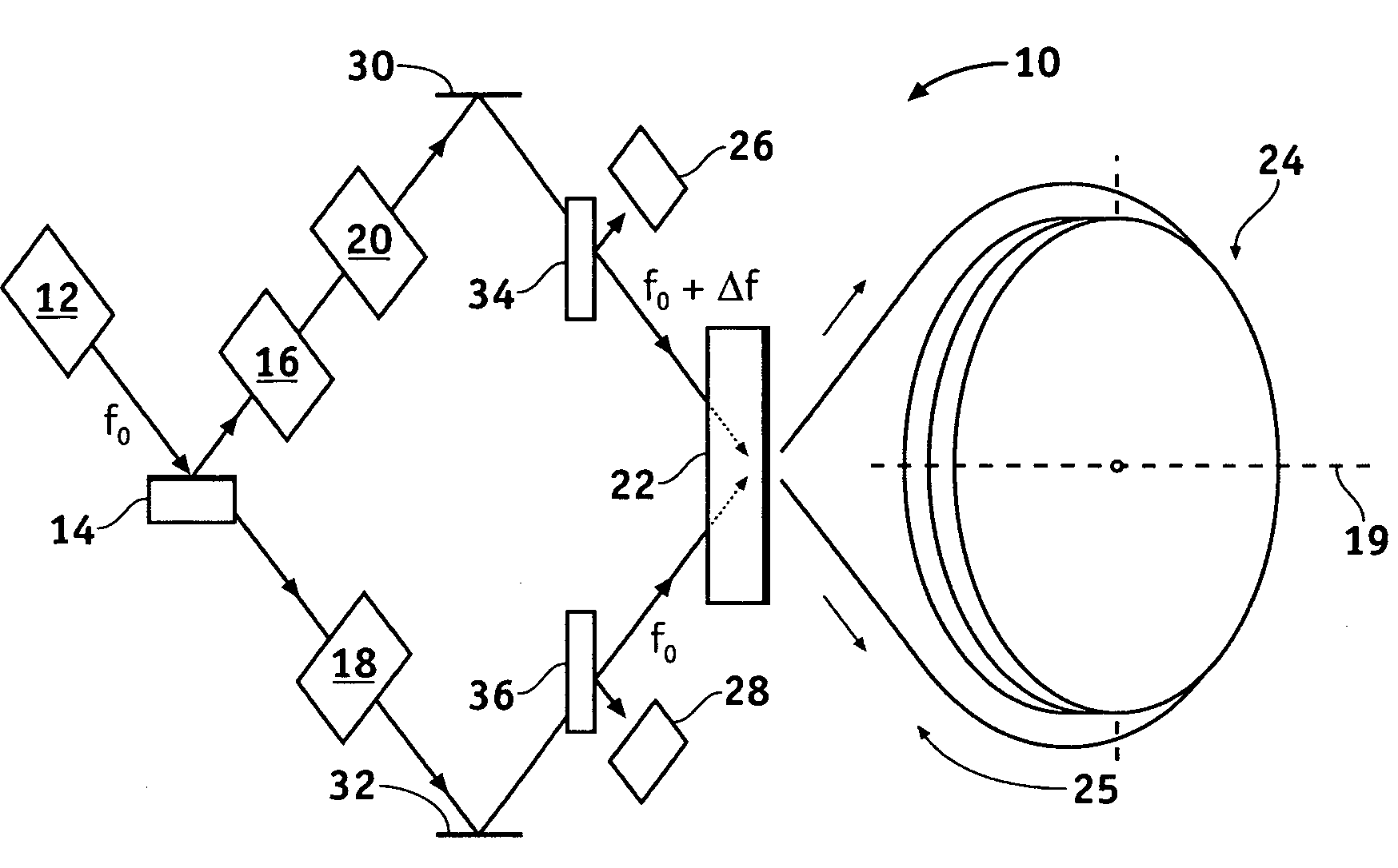
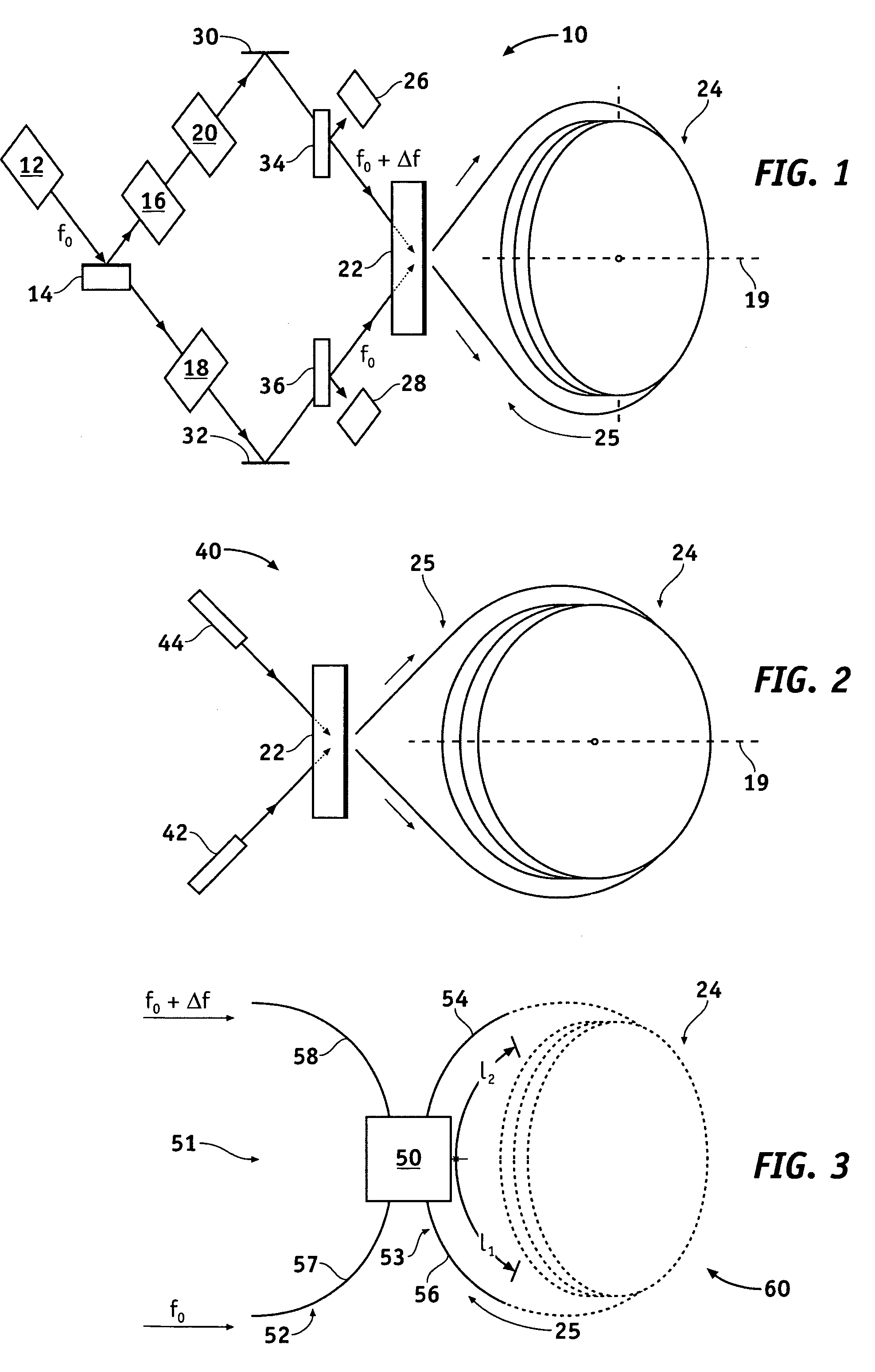
[0016]Referring now to the drawings, FIG. 1 is a schematic diagram of a resonator fiber optic gyro (RFOG) 10 in accordance with an exemplary embodiment of the present invention. The RFOG 10 includes a tunable light source 12 (e.g., a laser) configured to generate a light beam having a frequency f0, a beam splitter 14 configured to receive the light beam from the light source 12 and further configured divide the light beam from the light source 12 into first and second light beams, a first wave modulator 16 configured to receive the first light beam from the beam splitter 14 and further configured to modulate the first modulated light beam, a...


PUM


Abstract

Apparatus is provided for a fiber optic gyro. The fiber optic gyro includes a ring resonator having first and second counter-propagating directions. The ring resonator includes a coil having an axis and an optical fiber having a hollow core. The ring resonator is configured to produce a first resonance frequency when a first light beam circulates through the hollow core in the first counter-propagating direction and produce a second resonance frequency when a second light beam circulates through the hollow core in the second counter-propagating direction. A difference between the resonance frequencies indicates a rotation rate of the fiber optic gyro about the axis.

Description

CROSS REFERENCE TO RELATED APPLICATION[0001]This application claims the benefit of U.S. Provisional Application 60 / 648,163, filed Jan. 28, 2005.FIELD OF THE INVENTION[0002]The present invention generally relates to gyro systems, and more particularly relates to rotational sensors for use in a fiber optic gyro.BACKGROUND OF THE INVENTION[0003]Gyros have been used to measure rotation rates or changes in angular velocity about an axis. A basic conventional fiber optic gyro (FOG) includes a light source, a beam generating device, and a coil of optical fiber coupled to the beam generating device that encircles an area. The beam generating device transmits light beams into the coil that propagate in a clockwise (CW) direction and a counter-clockwise (CCW) direction along the core of the optical fiber. Many FOGs utilize glass-based optical fibers that conduct light along a solid core of the fiber. The two counter-propagating (CW and CCW) beams experience different pathlengths while propaga...

Claims


Application Information

Patent Timeline
Patent Type & Authority Patents(United States)
IPC IPC(8): G01C19/72
CPCG01C19/727
Inventor SANDERS, GLEN A.STRANDJORD, LEE K.
Owner HONEYWELL INT INC
Why Eureka
Try Eureka