
Public service message broadcasting system and method

a public service message and broadcasting system technology, applied in the field of emergency message broadcasting systems, can solve the problems of limited access, sms systems and technology have significant technical limitations, and existing systems do not provide location-based notification or broadcast messages

Active Publication Date: 2010-07-06
ENVISIONIT LLC
View PDF69 Cites 14 Cited by
  • Summary
  • Abstract
  • Description
  • Claims
  • Application Information

AI Technical Summary

Benefits of technology

The system enables simultaneous messaging to millions of subscribers with minimal network congestion, providing real-time, location-based emergency alerts without requiring pre-event recipient action or subscription fees, ensuring critical information reaches the public effectively during emergencies.

Problems solved by technology

Existing public service warning systems are antiquated and provide only limited access to the public who may be in need of knowing of potential emergencies or danger.
Additionally, existing systems do not provide for location-based notification or broadcast messages.
However, SMS systems and technology have significant technical limitations and experience with such systems has been disappointing due to significant delays in the delivery of SMS messages and negative impacts to the networks due to congestion.
This is due to the limited technical and network support for the service and is also due to the service being offered by Mobile Service Providers and wireless network providers on a subscription basis.
As such, use of the SMS service capability for emergency broadcasting is very limited.
Additionally, the use of SMS technology for broadcasting requires enormous network infrastructure utilization.
A telecommunication system can suffer from congestion, not only in its voice traffic channels, but also in its narrow-band data channels used for the SMS service.
Telecommunication networks are not designed or deployed to handle such high levels of simultaneous call attempts.
In the case of a large number of messages being attempted, a large number of roaming numbers will have to be assigned, perhaps exhausting the range of such numbers.
SMS service is not capable of location-specific messaging.
Additionally, SMS messaging places a considerable call processing load on the telecommunication system and infrastructure considering that the above process is multiplied by the demand of thousands or tens of thousands of SMS call set up requests at the same time.
The potential initiation of broadcast SMS volumes will not only affect network resources for SMS messaging, but also negatively affect ability of the telecommunication networks to set up and support voice traffic during any period of message broadcasting as these resources are shared by both services.
However, in this prior art system, SMS and Wireless Access Protocol (WAP) messaging utilize capacity on these channels making them unavailable for other purposes such as voice call set up.
Additionally, each of the SDCCH channels can only handle a limited number of SMS and / or WAP transmissions.
As such, during heavy messaging, the related high volumes of messaging traffic may have a negative affect on other services including the set up of voice calls.
However, this results in the loss of the traffic channel for voice communications.
This, however, occupies the traffic channel for a longer time than would otherwise be the case.
There is a limit on the number of traffic channels that can utilize this feature.
In most cases, only one traffic channel is converted thereby limiting the solution to 8 new SDCCH channels.
In high density cells, when a large quantity of SMS messaging traffic is offered, congestion occurs due to the each cell having over one hundred traffic channels within the cell.
However, such message load management negatively impacts the opportunity for using SMS messaging for broadcasting emergency messages to users of those networks.
Throttling often significantly delays the delivery of the SMS message, even though its timing delivery in an emergency is critical.
Furthermore, if a message fails to be delivered, the SMS center repeatedly attempts to deliver the message, thereby causing further congestion and message backlog.
While the cell broadcast capability is included in new telecommunications infrastructure being deployed, cell broadcasting systems and services have not been developed which effectively utilize the technology.

Method used


Image

  • Public service message broadcasting system and method
  • Public service message broadcasting system and method
  • Public service message broadcasting system and method

Examples


Embodiment Construction

[0040]The following description is merely exemplary in nature and is in no way intended to limit the invention, its application, or uses.

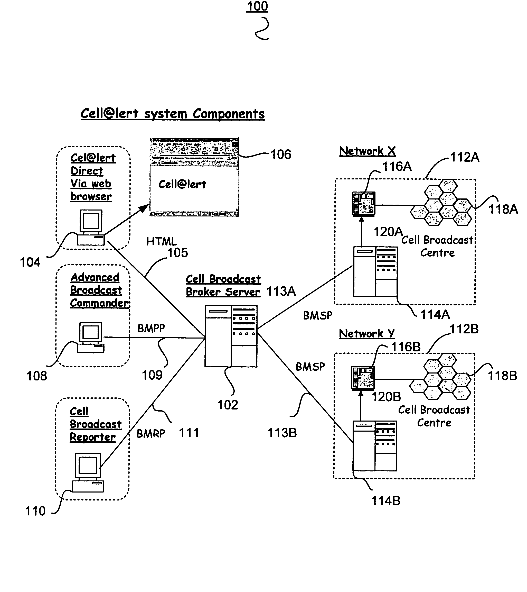
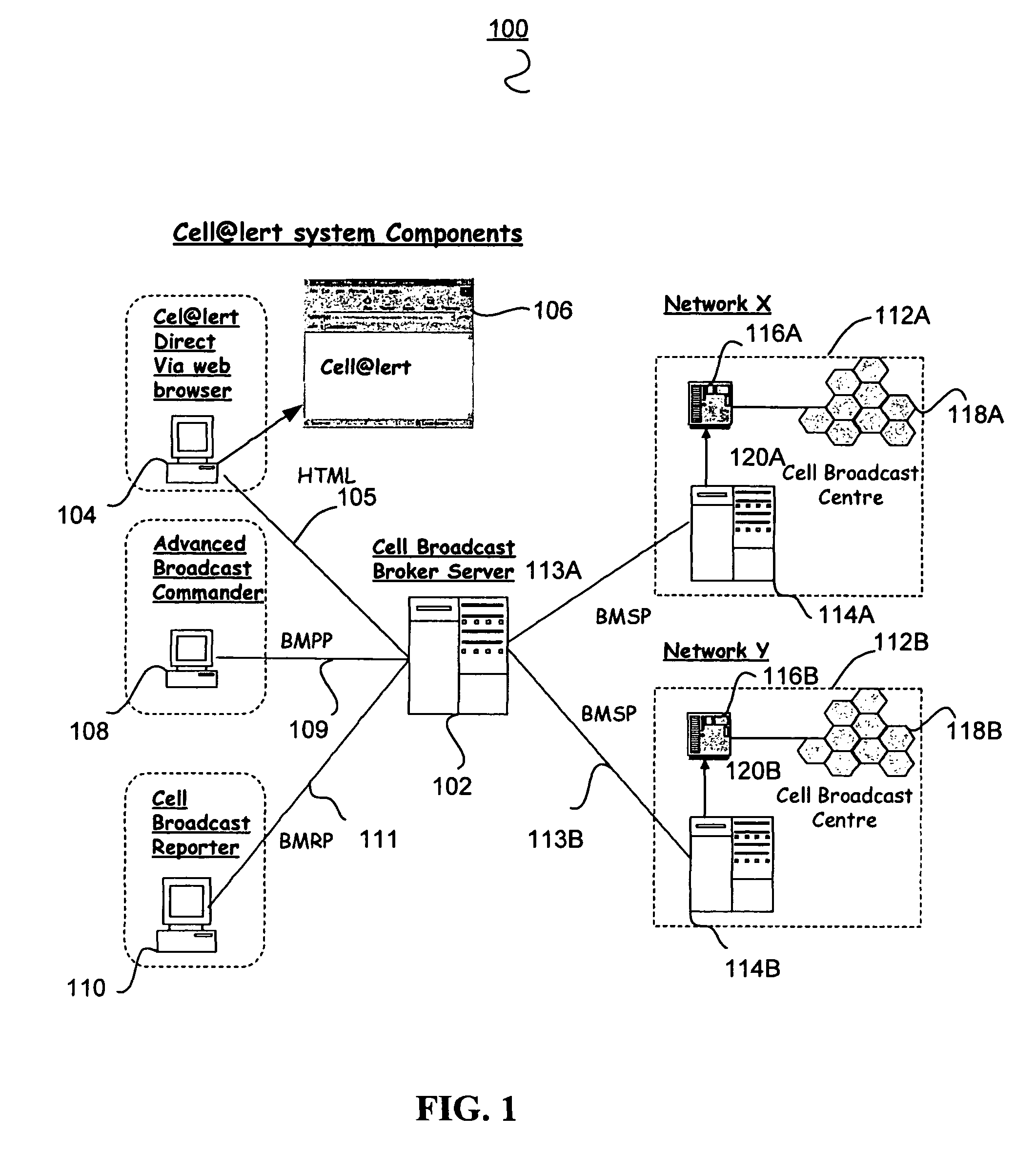
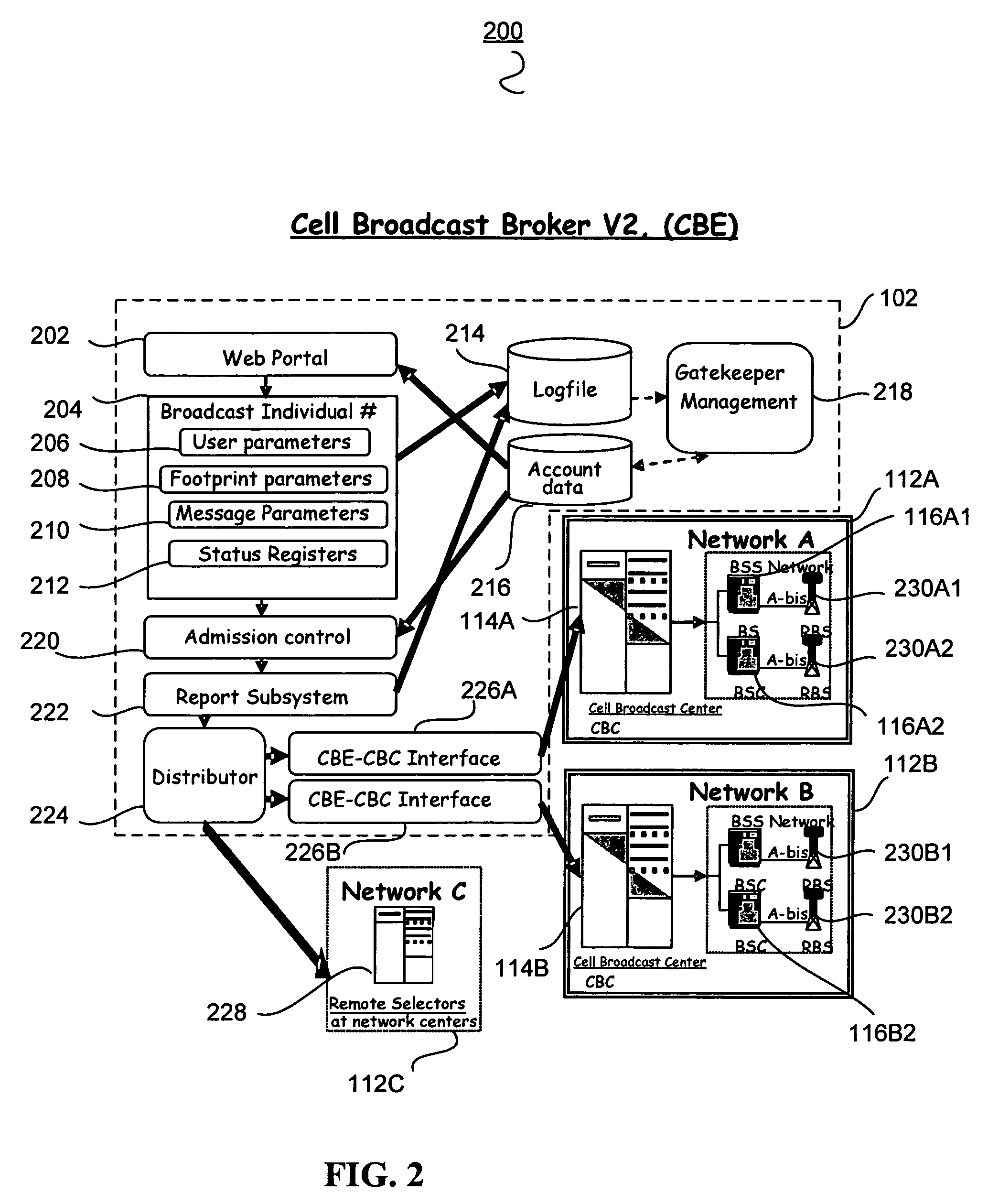
[0041]The public service message location broadcasting system (PLBS) according to one or more embodiments of the invention provide for an improved system and method for public service broadcast messaging. A public service message location broadcasting system (PLBS) operator provides a Broadcast Agent Web Portal or Webpage or other similar Graphical User Interface (GUI), implementation and maintenance of the networks' cell-broadcast messaging components, networks and platforms, administration and operation of the public service message location broadcasting system, and interfaces to local telecommunication service providers including mobile unit service providers.

[0042]According to one embodiment in the event of a serious public emergency, a short text message is sent over the location broadcast channel. A mobile unit or Broadcast Agent phone, which...


PUM


Abstract

The public service message location broadcast system and method provides for broadcasting a message to communication receiving devices located within a defined geographic broadcast target area. The broadcast target area is defined by a broadcast agent using a broadcast agent webpage and a broadcast service bureau transmits the broadcast message to one or more local carriers who provide telecommunication service to the broadcast target area. The local carrier transmits the broadcast message to targeted users within the broadcast target area.

Description

CROSS REFERENCE TO RELATED APPLICATIONS[0001]This application claims priority to Provisional U.S. Application Ser. No. 60 / 544,739, filed Feb. 13, 2004, the entire disclosure of which is incorporated herein by reference.FIELD OF THE INVENTION[0002]The present invention relates to emergency message broadcast systems and in particular location-specific public service message broadcasting.BACKGROUND OF THE INVENTION[0003]With the events of 9 / 11, there has been increased concern with the ability of present systems for providing public service broadcasting of messages and warnings to the public. Existing public service warning systems are antiquated and provide only limited access to the public who may be in need of knowing of potential emergencies or danger. Additionally, existing systems do not provide for location-based notification or broadcast messages.[0004]As such, there is a need for an improved method and system for providing timely information to the public related to potential ...

Claims


Application Information

Patent Timeline
Patent Type & Authority Patents(United States)
IPC IPC(8): G06F15/16H04M11/04H04W4/021H04W4/06H04W4/90H04W92/02
CPCH04L12/1895H04L12/5865H04L51/20H04W4/06H04W76/002H04H20/02H04W4/22H04W76/007H04W92/02H04W76/50H04W4/90H04W76/40H04W4/021H04W4/14H04L51/222H04L65/611
Inventor WEISER, DOUGLAS "BUD"PRESTON, KEVIN R.WOOD, MARK ANDREW
Owner ENVISIONIT LLC
Learn More