
Thermocouples

a technology of thermocouples and components, applied in the field of electromechanical devices, can solve the problems of reducing the service life and accuracy of embedded thermocouples, oxidation of thermocouples, and failure of thermal barrier coatings

Active Publication Date: 2010-07-13
CVD MESOSCRIBE TECH CORP
View PDF24 Cites 342 Cited by
  • Summary
  • Abstract
  • Description
  • Claims
  • Application Information

AI Technical Summary

Benefits of technology

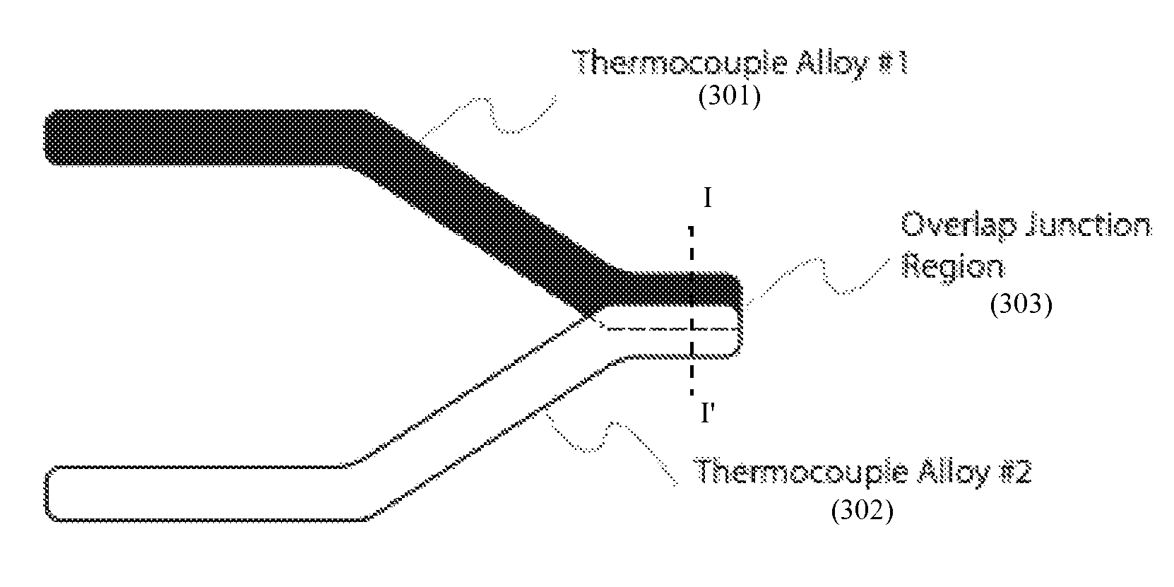
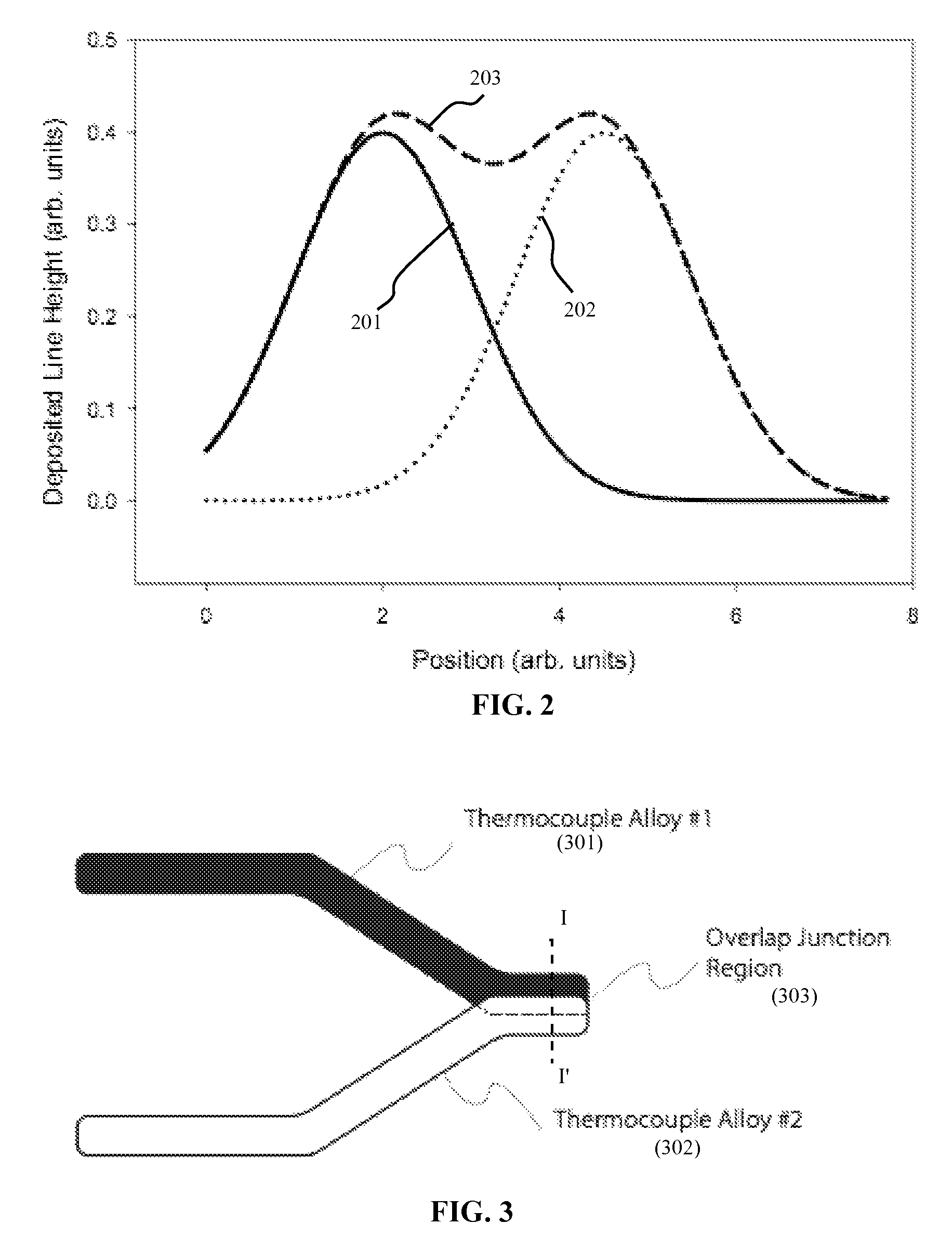
"The present patent describes a thermocouple that includes a junction that connects two legs of thermoelectric material. The junction has a similar height to the legs. The thermocouple can be formed by continuously varying the composition of a line over a portion of the line, resulting in a graded junction with the height of the conducting line. The thermocouple also includes at least first and second thermocouple legs each having an alloy composition, and a plurality of isothermal contact pads for electrically coupling the legs to collect a signal. The technical effect of this invention is to provide a more efficient and accurate thermocouple for measuring temperature."

Problems solved by technology

There are various problems that reduce component survival, service lifetime and accuracy for embedded thermocouples in harsh thermal environments in the presence of oxidizing or other reactive gases.
These problems include failure of the thermal barrier coating including cracking and spalling, oxidation of the thermocouple, and temperature measurement errors caused by the use of non-standard thermocouple alloy compositions.
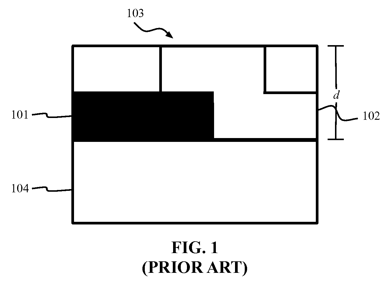
The added thickness has several possible detrimental effects.
Furthermore, the region where the top coating passes over the edge of the bottom layer is a high stress region prone to cracking or other failure modes.

Method used


Image

  • Thermocouples
  • Thermocouples
  • Thermocouples

Examples


Embodiment Construction

[0020]According to an embodiment of the present disclosure, a thermocouple device has desirable durability and accuracy. The thermocouple device may be implemented as a low profile thermocouple, a graded junction low profile thermocouple, a three terminal thermocouple, or direct write thermal spray type thermocouple, among others.

[0021]The thermocouples can be embedded in a thermal barrier coating (TBC) used to protect a substrate from the high temperature combustion gases. These embedded thermocouples need to have a long service life and may be used to monitor the condition of the substrate, e.g., components of machinery operating in harsh environments.

[0022]The TBC comprises several layers that work in concert to protect the substrate metal, such as a superalloy. An upper layer of the TBC may be yttria stabilized zirconia (YSZ) deposited on a bond coat of an alloy containing aluminum, for example NiCrAlY. The YSZ forms an interface layer of Al2O3 by thermal oxidation of the bond c...


PUM

PropertyMeasurementUnit
lengthaaaaaaaaaa
temperaturesaaaaaaaaaa

Abstract

A thermocouple disposed on a substrate comprises a first leg of thermoelectric material, a second leg of thermoelectric material, and a thermocouple junction electrically connecting the first leg and the second leg, wherein a height of the thermocouple junction is substantially a height of the first or second legs.

Description

CROSS-REFERENCE TO RELATED APPLICATION[0001]This application claims priority to U.S. Provisional Application Ser. No. 60 / 788,220, filed on Mar. 31, 2006, which is herein incorporated by reference in its entirety.BACKGROUND OF THE INVENTION[0002]1. Technical Field[0003]The present invention relates to electronic devices, and more particularly to a thermocouple and methods of fabricating thermocouples.[0004]2. Discussion of Related Art[0005]Thermocouples measure temperature. Thermocouples include two dissimilar metals, joined together at one end, which produce a small unique voltage for a given temperature. This voltage is measured and interpreted by a thermocouple thermometer.[0006]There are various problems that reduce component survival, service lifetime and accuracy for embedded thermocouples in harsh thermal environments in the presence of oxidizing or other reactive gases. These problems include failure of the thermal barrier coating including cracking and spalling, oxidation of...

Claims


Application Information

Patent Timeline
Patent Type & Authority Patents(United States)
IPC IPC(8): G01K7/02H01L35/28H10N10/10H10N10/80H10N10/85
CPCG01K7/04H01L35/08H01L35/20H10N10/854H10N10/817
Inventor GAMBINO, RICHARD J.LONGTIN, JON PATRICKBROGAN, JEFFREY A.GUTLEBER, JONATHAN S.GREENLAW, ROBERT J.
Owner CVD MESOSCRIBE TECH CORP
Learn More