

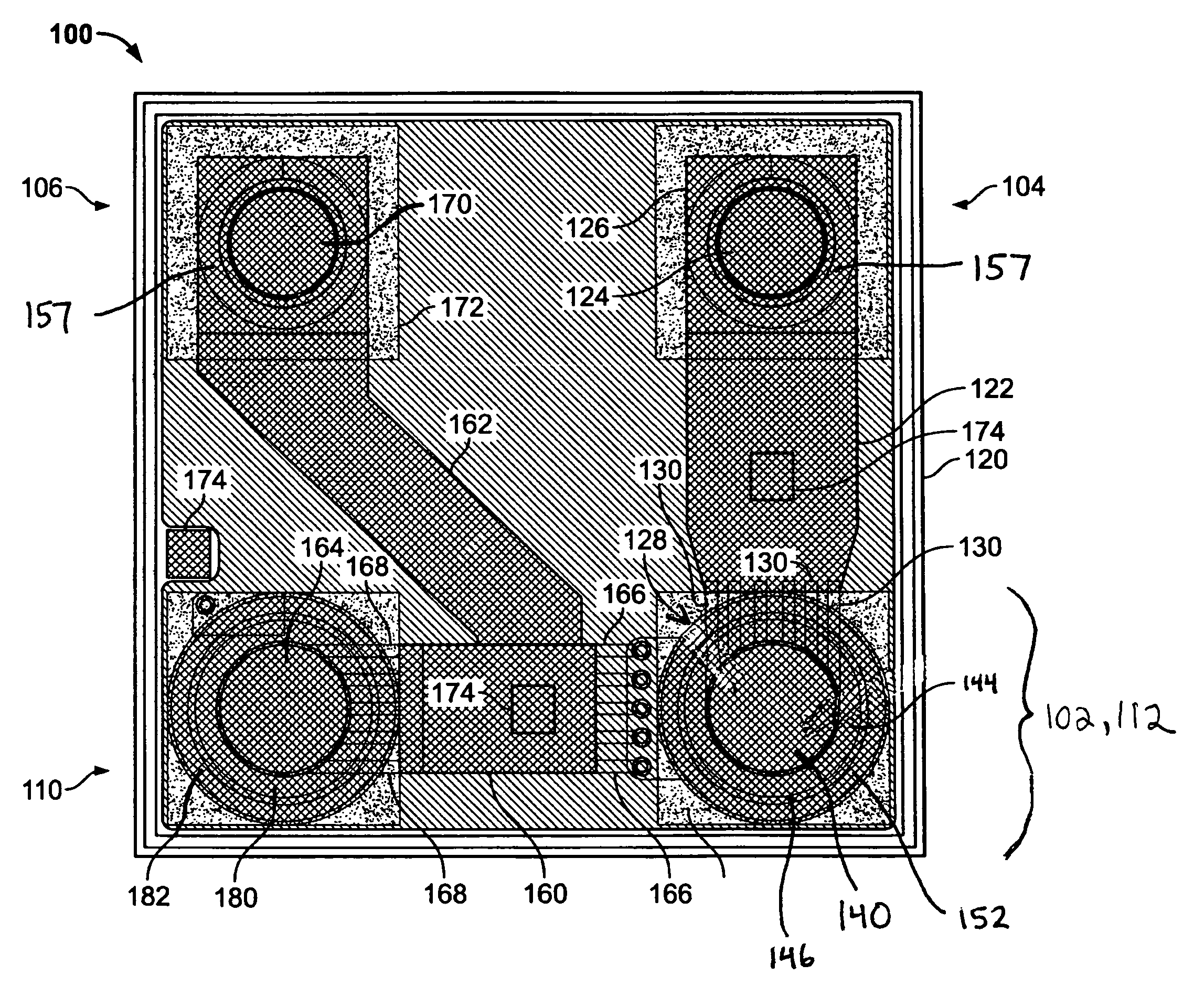
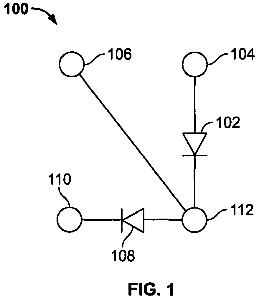
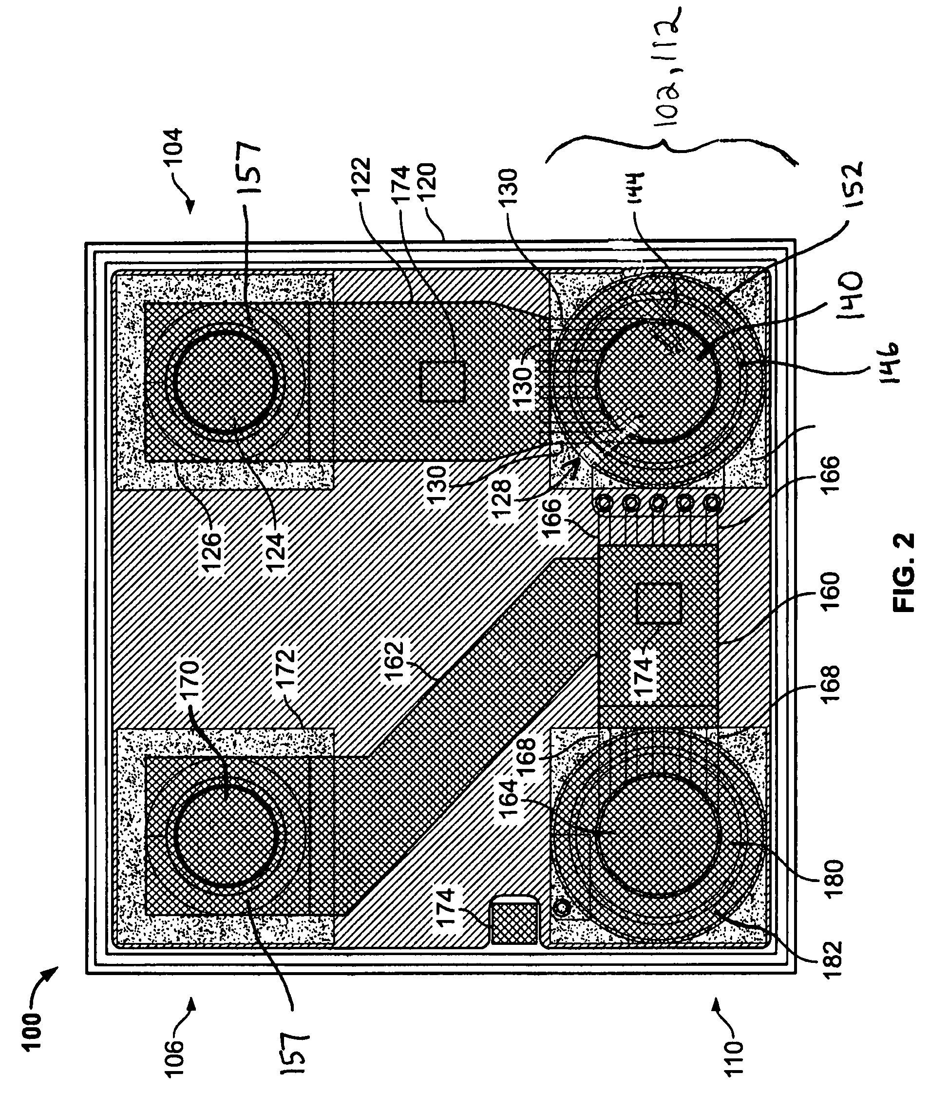
Series-shunt switch with thermal terminal
a series-shunt switch and thermal terminal technology, applied in the field of switches, can solve the problems of affecting circuit performance, affecting circuit performance, and difficult design of melf packages to include heat transfer conduits
- Summary
- Abstract
- Description
- Claims
- Application Information
AI Technical Summary
Benefits of technology
Problems solved by technology
Method used
Image

Examples
Embodiment Construction
[0013]For simplicity and ease of explanation, the invention will be described herein in connection with various embodiments thereof. Those skilled in the art will recognize, however, that the features and advantages of the various embodiments may be implemented in a variety of configurations. It is to be understood, therefore, that the embodiments described herein are presented by way of illustration, not of limitation.
[0014]As used herein, an element or step recited in the singular and proceeded with the word “a” or “an” should be understood as not excluding plural said elements or steps, unless such exclusion is explicitly stated. Furthermore, references to “one embodiment” of the present invention are not intended to be interpreted as excluding the existence of additional embodiments that also incorporate the recited features. Moreover, unless explicitly stated to the contrary, embodiments “comprising” or “having” an element or a plurality of elements having a particular property...
PUM
 Abstract
Description
Claims
Application Information