
Operational amplifier with resistance switch crossbar feedback

a crossbar feedback and resistance switch technology, applied in the field of control circuits, can solve problems such as improved operation

Inactive Publication Date: 2010-07-13
MOUTTET BLAISE LAURENT
View PDF13 Cites 17 Cited by
  • Summary
  • Abstract
  • Description
  • Claims
  • Application Information

AI Technical Summary

Benefits of technology

This approach enables the circuits to adjust to environmental variations and different applications, enhancing functionality and stability by allowing for a large number of possible configurations and automatic optimization of parameters like bandwidth and settling time.

Problems solved by technology

However, environmental effects such as changes in temperature or humidity may alter circuit parameters used in analog processing leading to improper operation.

Method used


Image

  • Operational amplifier with resistance switch crossbar feedback
  • Operational amplifier with resistance switch crossbar feedback
  • Operational amplifier with resistance switch crossbar feedback

Examples


Embodiment Construction

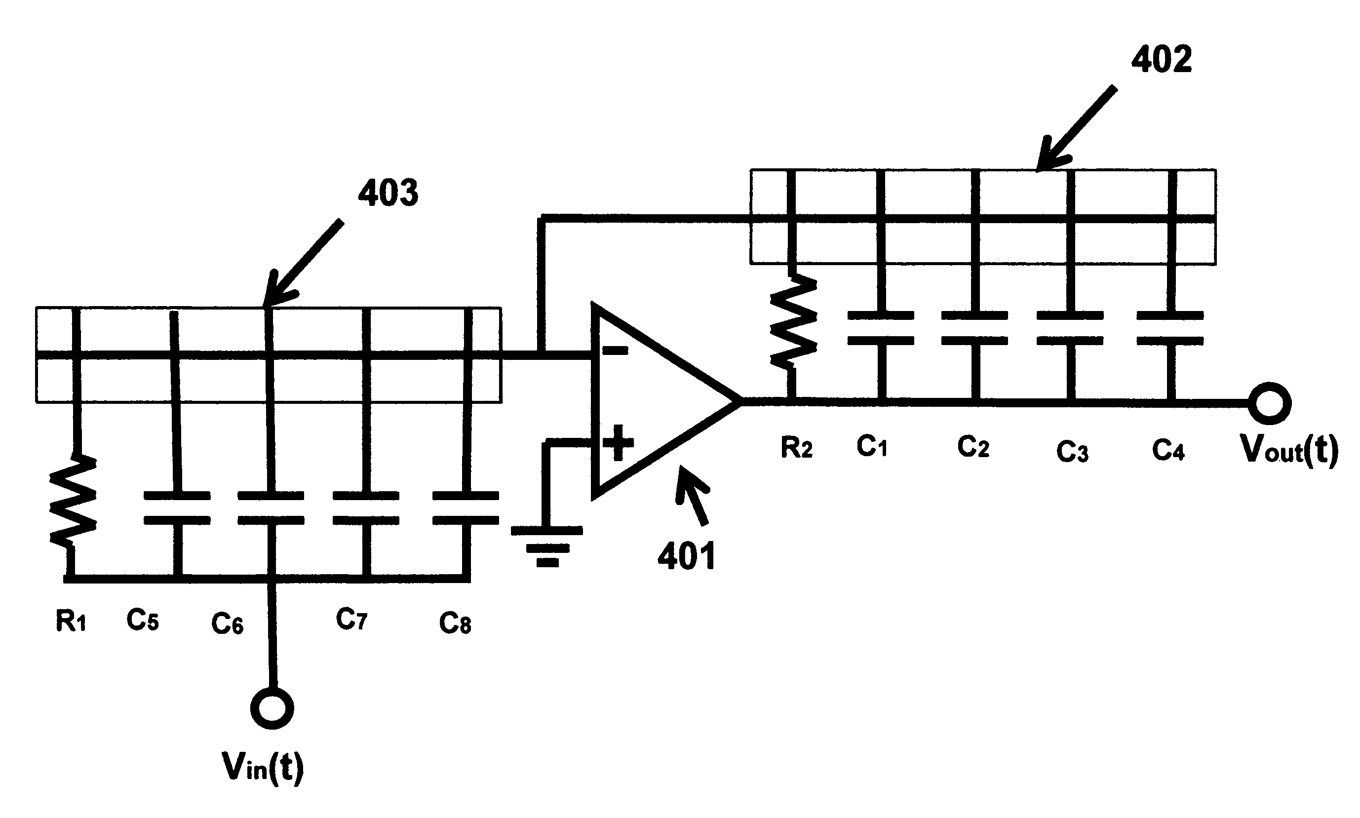
[0014]As illustrated in FIG. 3, an operational amplifier 301 includes an inverting input, a non-inverting input and an output connection. An input resistor R1 is connected between an input electrode and the inverting terminal of the operational amplifier 301. A resistor R2 and an array of capacitors C1-C4 are electrically connected between the output of the operational amplifier 301 and a resistance switch crossbar array 302. The resistance switch crossbar array 302 may be formed from intersecting conductive wires which sandwich a resistance switching material such as chalcogenides, conducting polymers, perovskites, rotaxane or catenane molecules, or bilayer oxides as known to the art. The crossbar array may also be formed based on micromechanical or nanomechanical switches formed of carbon nanotubes as used in nanotube RAM designs developed by the company Nantero. As illustrated in FIG. 3 the crossbar array 302 has one row and five columns and each intersection of the crossbar arra...


PUM


Abstract

A control circuit includes an operational amplifier having an inverting input, a non-inverting input, and an output, an array of impedance elements including capacitors are connected to the output of the operational amplifier, and a resistance switch crossbar array configured to store data in the form of high or low resistance states, wherein the resistance switch crossbar array is electrically connected between the array of impedance elements and the inverting input of the operational amplifier. The crossbar control circuit may be implemented in a control system to provide for adjustment of the control system to changes in environmental conditions or to change the function of the control system.

Description

[0001]This patent application is a Continuation-In-Part of U.S. patent application Ser. No. 11 / 976,927, filed Oct. 30, 2007, now U.S. Pat. No. 7,609,086 which is a Continuation-In-Part of U.S. patent application Ser. No. 11 / 798,647, filed May 16, 2007, which is a Continuation-In-Part of U.S. patent application Ser. No. 11 / 395,237, filed Apr. 3, 2006, issued as U.S. Pat. No. 7,302,513.FIELD OF THE INVENTION[0002]The present invention pertains to a control circuit using a crossbar switching architecture suitable for applications in signal processing, morphware, and robotics.BACKGROUND AND BRIEF DESCRIPTION OF THE INVENTION[0003]As disclosed in parent U.S. patent application Ser. Nos. 11 / 976,927, 11 / 798,647, and 11 / 395,237, which are each incorporated by reference in their entirety, crossbar circuit architectures may be configured to provide for programmable signal processors. The present patent application provides further embodiments of such systems to provide adaptive control system...

Claims


Application Information

Patent Timeline
Patent Type & Authority Patents(United States)
IPC IPC(8): H03F1/36
CPCH03F1/34H03G5/00
Inventor MOUTTET, BLAISE LAURENT
Owner MOUTTET BLAISE LAURENT
Learn More