
System and method for setting functions according to location

a technology of location and function, applied in the field of system for setting functions in vehicles, can solve the problems of affecting the quality of life of many people, their accompanying annoyances have correspondingly increased, and the conventional vehicular alarm system is not always per

Inactive Publication Date: 2010-07-13
GROSSMAN VICTOR A
View PDF6 Cites 151 Cited by
  • Summary
  • Abstract
  • Description
  • Claims
  • Application Information

AI Technical Summary

Benefits of technology

"The present invention provides a mobile device and method for automatically protecting vehicles and setting various alarm functions based on location data. The system can comply with local ordinances without user intervention and can be activated using location information from GPS or base stations. The system can also display information relating to regulations and can set functions based on predetermined settings or user preferences. The technical effects of the invention include improved security for vehicles, automation of various alarm functions, and enhanced user experience."

Problems solved by technology

As conventional vehicular alarm systems become more commonplace, their accompanying annoyances have correspondingly increased.
Thus, although conventional active vehicular alarm systems are designed to draw attention, they may do so repeatedly and for the wrong reason.
Unfortunately, conventional vehicular alarm systems are not always perfect, and frequently experience false alarms which can contribute to noise pollution impacting the quality of life of many people, especially those in urban areas.
Each year it is estimated that millions of dollars in cities alone are lost because of noise pollution.
It has been said that the noise pollution emitted by car alarms is responsible for hundreds of millions of dollars of lost income each year.
Conventional vehicle alarm systems are known to commonly experience false alarms for many reasons.

Method used


Image

  • System and method for setting functions according to location
  • System and method for setting functions according to location
  • System and method for setting functions according to location

Examples


Embodiment Construction

[0033]Preferred embodiments of the present invention will now be described in detail with reference to the drawings. For the sake of clarity, certain features of the invention will not be discussed when they would be apparent to those with skill in the art.

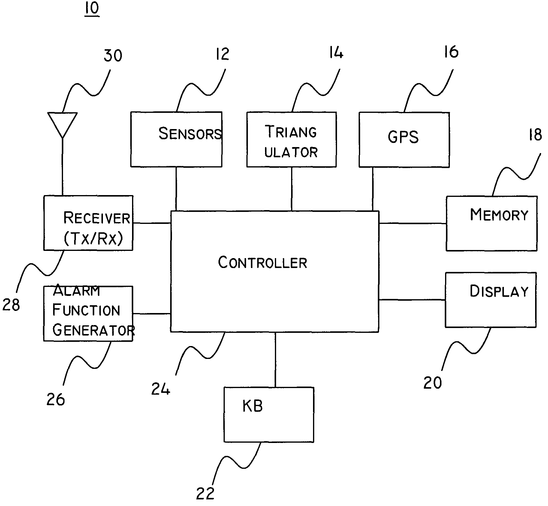
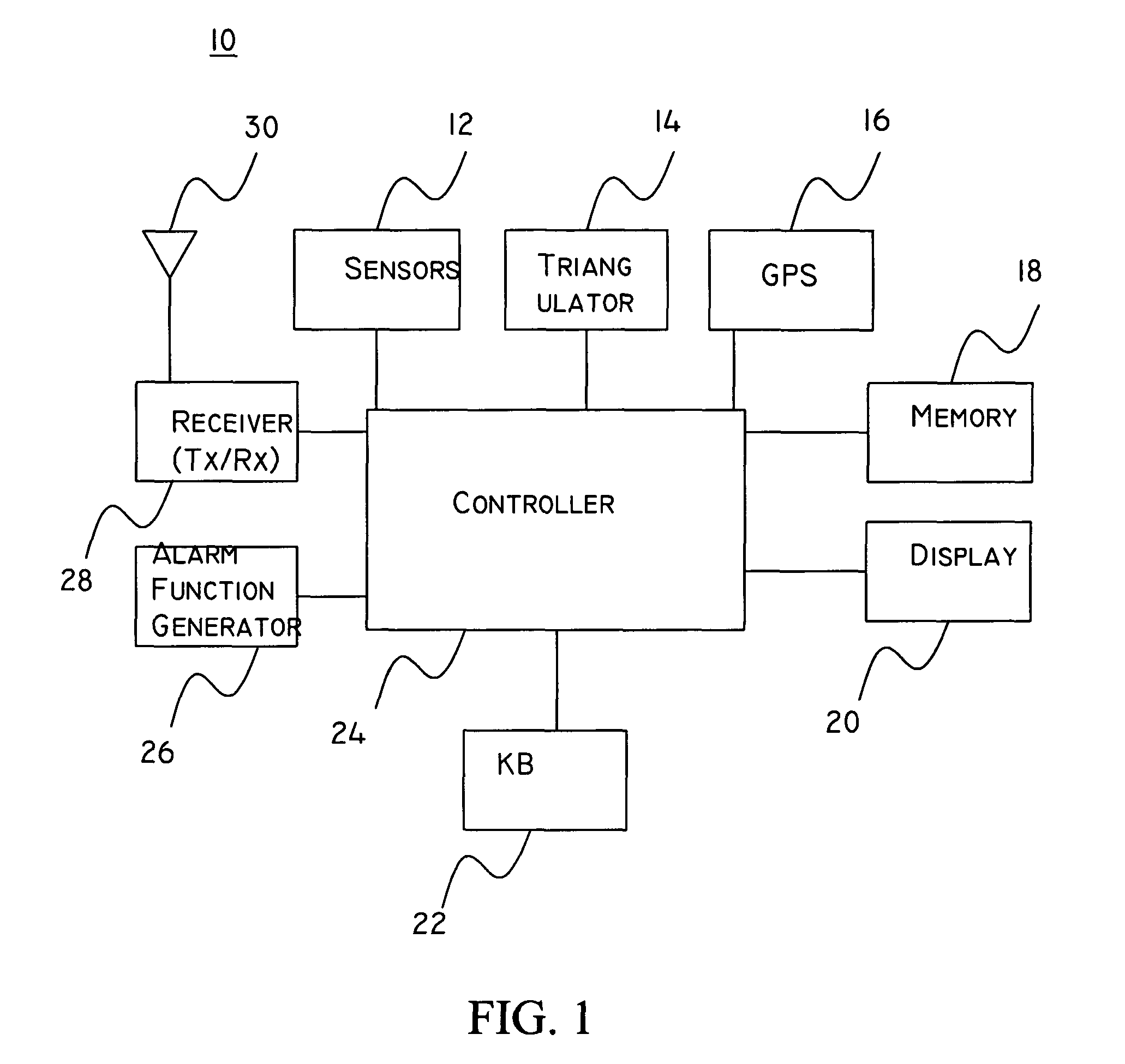
[0034]A block diagram illustrating a vehicular alarm according to the present invention is shown in FIG. 1. The alarm system includes at least one mobile station 10 (hereinafter alarm system 10) which includes a controller 24, an optional display 20, a memory 18, a GPS (global positioning system) module 16, sensors 12, an alarm function generator 26, a transceiver (or optional receiver) 28, and an antenna 30. The alarm system 10 can include any or all of the various components or can interface with external components to obtain necessary data. For example, the alarm system can interface with another computer (e.g., an on-board GPS system) via a PC (Personal Computer) interface, an RS 232 serial interface, a USB (Universal Serial B...


PUM


Abstract

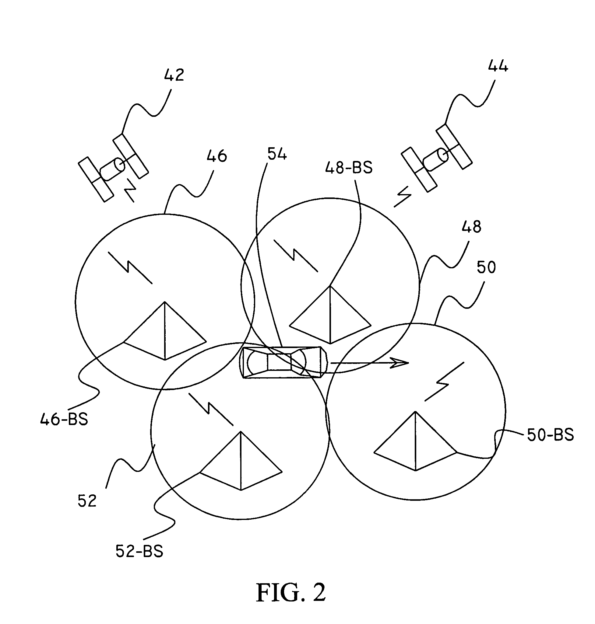
An apparatus, system, and method for controlling functions of a vehicular alarm. The method includes receiving one or more signals including location information, determining a location of the vehicle using the location information, setting one or more functions based on the location information, determining whether an alarm function is activated, and activating the one or more functions according to the setting upon determining that an alarm has been activated. The method may further include using GPS data or signals transmitted from one or more base stations (e.g., from cellular telephone base stations, computer networks, proprietary transmitters, etc.) to determine the position of the apparatus (e.g., installed in the vehicle). The apparatus may also inform a user of regulations relating to an area dependent upon its location.

Description

FIELD OF THE INVENTION[0001]The present invention relates generally to system for setting functions in vehicles, and more particularly to an apparatus and method for activating various functions based on location.BACKGROUND OF THE INVENTION[0002]As conventional vehicular alarm systems become more commonplace, their accompanying annoyances have correspondingly increased. Thus, although conventional active vehicular alarm systems are designed to draw attention, they may do so repeatedly and for the wrong reason. When activated, conventional alarms use lights, or audible alarms (such as sirens, horns, speakers, etc.) and / or wirelessly page an owner. Unfortunately, conventional vehicular alarm systems are not always perfect, and frequently experience false alarms which can contribute to noise pollution impacting the quality of life of many people, especially those in urban areas. Each year it is estimated that millions of dollars in cities alone are lost because of noise pollution. Acco...

Claims


Application Information

Patent Timeline
Patent Type & Authority Patents(United States)
IPC IPC(8): B60R25/10B60R25/04
CPCB60R25/04B60R25/33B60R25/00G08B21/0261G08B29/22G08B13/1427B60W2756/10G06F3/01B60R25/01B60W10/08B60W10/30B60W50/082B60W50/12B60W50/14B60W2050/143B60W2710/0677B60W2710/30G06F3/0482G06F3/0488G06F3/16
Inventor GROSSMAN, VICTOR A.
Owner GROSSMAN VICTOR A
Learn More