Method and system to compensate for banding defects

a banding defect and banding technology, applied in the field of document processing systems, can solve problems such as errors in the mechanical motion of rotating components, significant contributors of artifacts, and line spacing variations,

Inactive Publication Date: 2010-07-13
XEROX CORP
View PDF11 Cites 21 Cited by
  • Summary
  • Abstract
  • Description
  • Claims
  • Application Information

AI Technical Summary

Benefits of technology

[0015]The exemplary embodiment proposes a method and system to vary the rotational speed of the photoreceptor shaft slightly and periodically to modulate exposure per unit area on the photoreceptor surface. By controlling the exposure per unit area using the photoreceptor speed, the system is able to compensate for banding print defects.

Problems solved by technology

The scan line spacing variation is a significant contributor of artifacts in the marking process.
For example, halftone banding caused by scan line spacing variation is one of the most visible and undesirable artifacts, appearing as light and dark streaks across a printed page perpendicular to the process direction.
It is often periodic and it can result from errors in the mechanical motion of rotating components within a marking engine.
Banding phase is difficult to measure since, relative to the printed page, it varies from page to page.
Thus, if one measured page one, and determined that the phase was such that a density peak occurs at the beginning of each page, upon applying a corresponding compensation to page two, poor performance would result—the banding may even be enhanced by the control system, rather than suppressed.
The problem is that the banding source is not synchronous with the print.
Thus, one cannot use the print as a phase reference.
Actuation problems for banding compensation also occur.
For example, in using the image itself for banding compensation, phase synchronization is difficult as the page is usually not synchronous with the banding source.
Further, use of the image has limitations in solid areas in terms of amplitude quantization and in the potentially high cost of image computations.
Use of exposure modulation for banding compensation can also have limitations in terms of exposure bandwidth, noise rejection, and potentially high cost exposure system modifications.
However, the shaft encoder typical of these systems does not measure the photoreceptor surface velocity, which is the key parameter for banding print defects.
Further, encoders can have run-out and have their own inherent error sources.

Method used


Image

  • Method and system to compensate for banding defects
  • Method and system to compensate for banding defects
  • Method and system to compensate for banding defects

Examples


Embodiment Construction

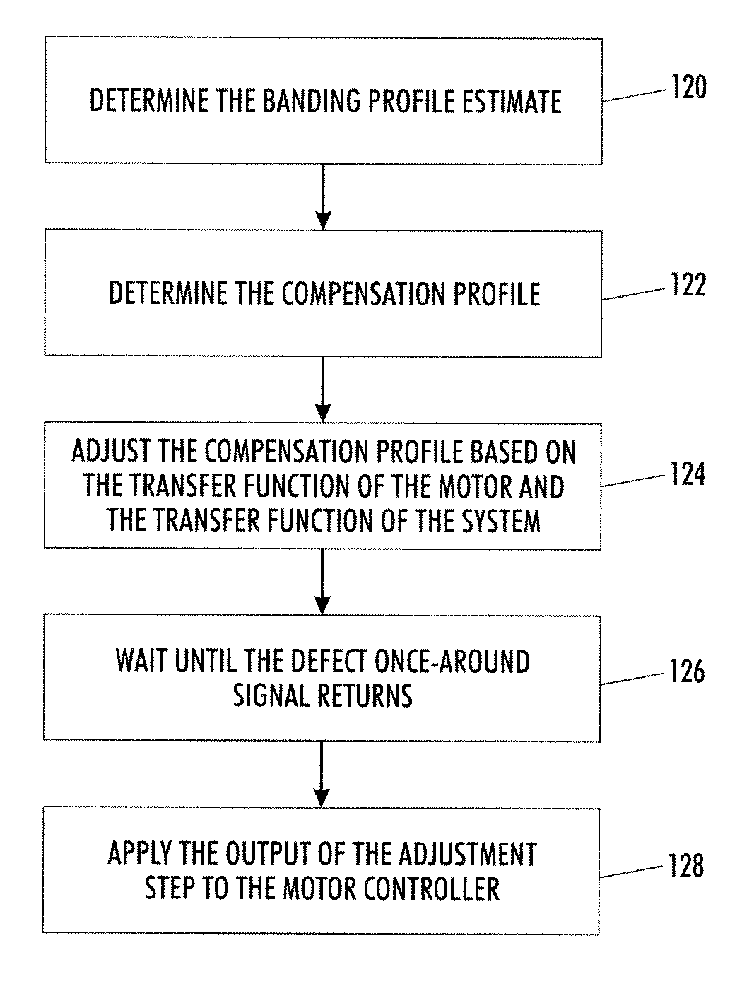
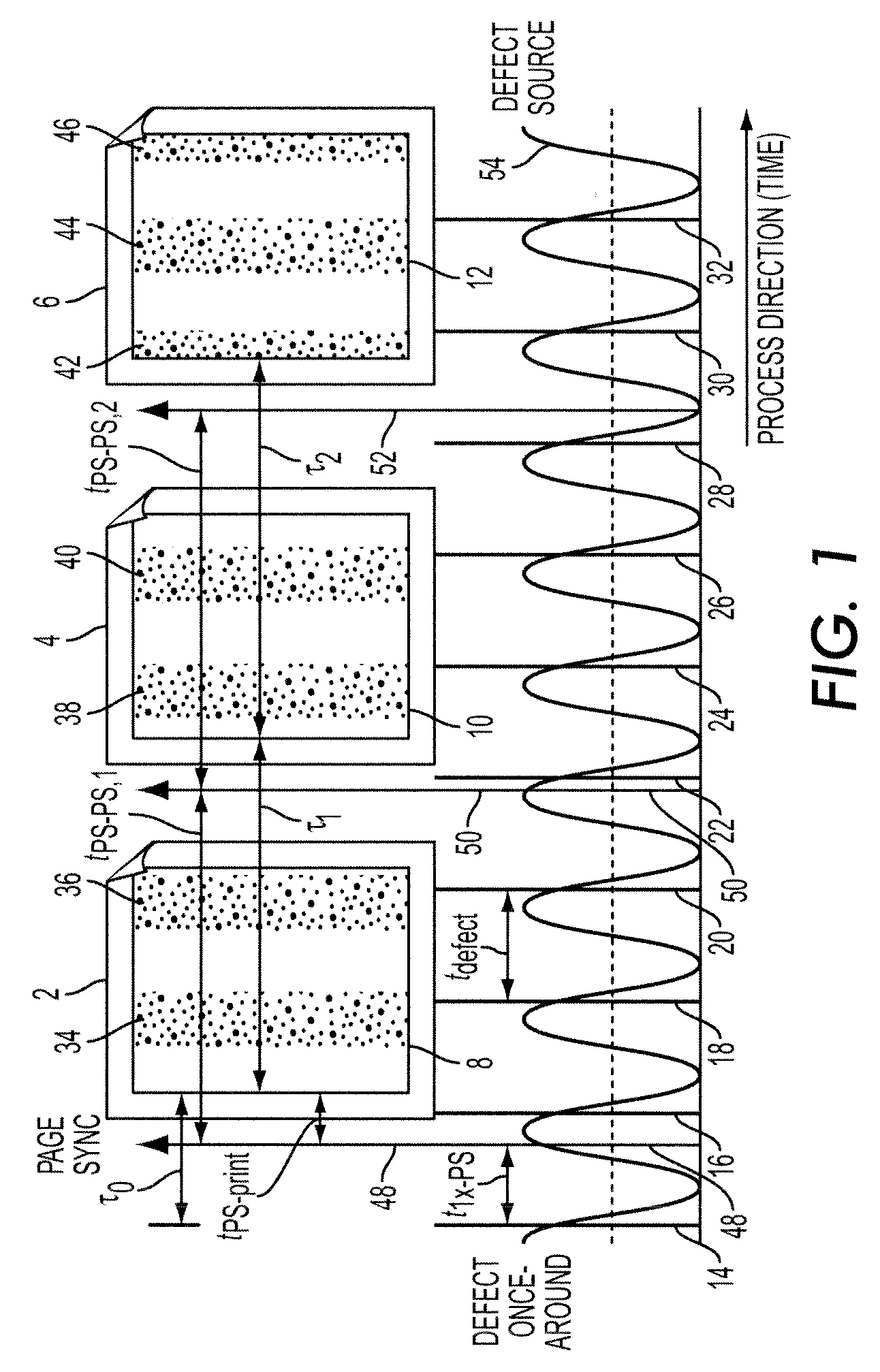
[0029]Referring now to the drawings wherein the showings are for purposes of illustrating the exemplary embodiments only and not for purposes of limiting the claimed subject matter, a series of images processed by a printing system in a process direction (i.e., the direction of the paper travel in the printing system) is shown in FIG. 1. Consider a print job of M pages, the first three of which are shown in FIG. 1. The boxes with the folded upper right hand corners depict pieces of paper 2, 4, and 6 with printed images or test targets 8, 10, and 12, respectively. They could represent any known sampling interval, such as interdocument zones, customer image zones, or printed pages. The images 8, 10, and 12 on the pieces of paper 2, 4, and 6 represent test targets designed for defect estimation. In the absence of banding defects, the printed test image should be a uniform midtone (i.e., approximately 50% area coverage). Because of banding from mechanical components within the printer, ...


PUM


Abstract

A method of correcting periodic banding defects in a printing system is provided. The method comprises: determining a banding profile estimate; determining a compensation profile; adjusting the compensation profile based on the transfer function of a motion system and the transfer function of a printing system; waiting until a defect once-around signal returns; and applying the output of the adjustment step to a controller controlling the speed of an imaging surface.

Description

CROSS REFERENCE TO RELATED PATENTS AND APPLICATIONS[0001]The following patents and applications, the disclosures of each being totally incorporated herein by reference, are mentioned:[0002]U.S. Pat. No. 7,054,568, entitled “METHOD AND APPARATUS FOR CONTROLLING NON-UNIFORM BANDING AND RESIDUAL TONER DENSITY USING FEEDBACK CONTROL,” to Mizes et al.;[0003]U.S. Pat. No. 7,058,325, entitled “SYSTEMS AND METHODS FOR CORRECTING BANDING DEFECTS USING FEEDBACK AND / OR FEEDFORWARD CONTROL, to Hamby et al.;[0004]U.S. Publication No. 2007 / 0139509 published Jun. 21, 2007, entitled “COMPENSATION OF MPA POLYGON ONCE AROUND WITH EXPOSURE MODULATION,” by Howard A. Mizes et al.;[0005]U.S. application Ser. No. 11 / 399,100 (Attorney Docket 20051634-US-NP), filed Apr. 6, 2006, entitled “SYSTEMS AND METHODS TO MEASURE BANDING PRINT DEFECTS,” by Peter Paul; and[0006]U.S. application Ser. No. 11 / 769,044 Attorney Docket 20061185-US-NP), entitled BANDING PROFILE ESTIMATOR USING MULTIPLE SAMPLING PERIODS, by Pe...

Claims


Application Information

Patent Timeline
Patent Type & Authority Patents(United States)
IPC IPC(8): H04N1/409G03G21/14H04N1/29H04N1/58G03G15/00
CPCB41J29/393G06K15/1219
Inventor PAUL, PETERRABBANI, SAHANDNOWAK, WILLIAM J.
Owner XEROX CORP
Why Eureka
Try Eureka