RFID tag modification for full depth backscatter modulation

a backscatter modulation and tag technology, applied in the field of wireless communication systems, radio frequency identification devices, wireless communication methods, radio frequency identification device communications methods, can solve the problem that tags have not been able to produce full depth modulation in some designs, and achieve the effect of reducing the impedance change of detector diodes, increasing impedance change, and increasing the impedance chang

Inactive Publication Date: 2010-07-20
BATTELLE MEMORIAL INST
View PDF19 Cites 6 Cited by
  • Summary
  • Abstract
  • Description
  • Claims
  • Application Information

AI Technical Summary

Benefits of technology

[0006]Other aspects of the invention provide a modulated backscatter radio frequency identification device comprising a diode detector configured to selectively modulate a reply signal onto an incoming continuous wave; communications circuitry configured to provide a modulation control signal to the diode detector, the diode detector being configured to modulate the reply signal in response to be modulation control signal; and circuitry configured to increase impedance change at the diode detector. The detector diode impedance change is reduced when the diode detector rectifies the incoming continuous wave while modulating the reply signal, whereby reducing the rectified signal increases impedance change by removing the reverse bias effects.
[0007]Yet other aspects of the invention provide a method of improving depth of modulation in a modulated backscatter radio frequency identification device including a diode detector configured to selectively modulate a reply signal onto an incoming continuous wave and communications circuitry configured to provide a modulation control signal to the diode detector, the diode detector being configured to modulate the reply signal in response to the modulation control signal, the method comprising increasing impedance change at the diode detector. The depth of modulation is a function of the impedance change whereby increasing the diode detector's impedance change also increases the depth of modulation and the range at which the tag's response can be read. This would otherwise not occur because the diode detector rectifies the incoming continuous wave while modulating the reply signal, whereby reducing the rectified signal increases modulation depth by removing the reverse bias effects on impedance changes.

Problems solved by technology

For superior tag receive sensitivity, the tag has not been able to produce full depth modulation in some designs.

Method used


Image

  • RFID tag modification for full depth backscatter modulation
  • RFID tag modification for full depth backscatter modulation
  • RFID tag modification for full depth backscatter modulation

Examples


Embodiment Construction

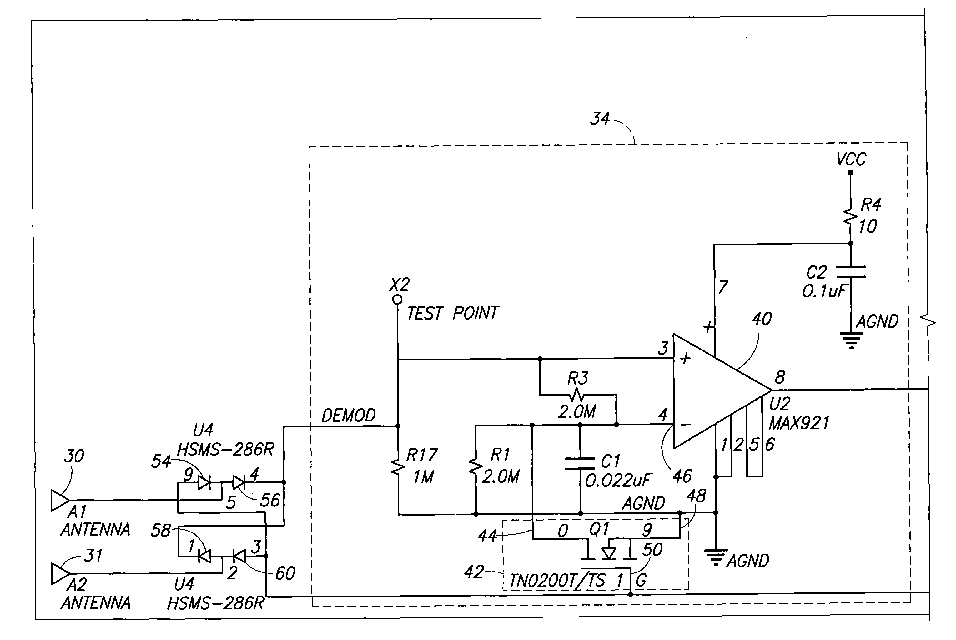
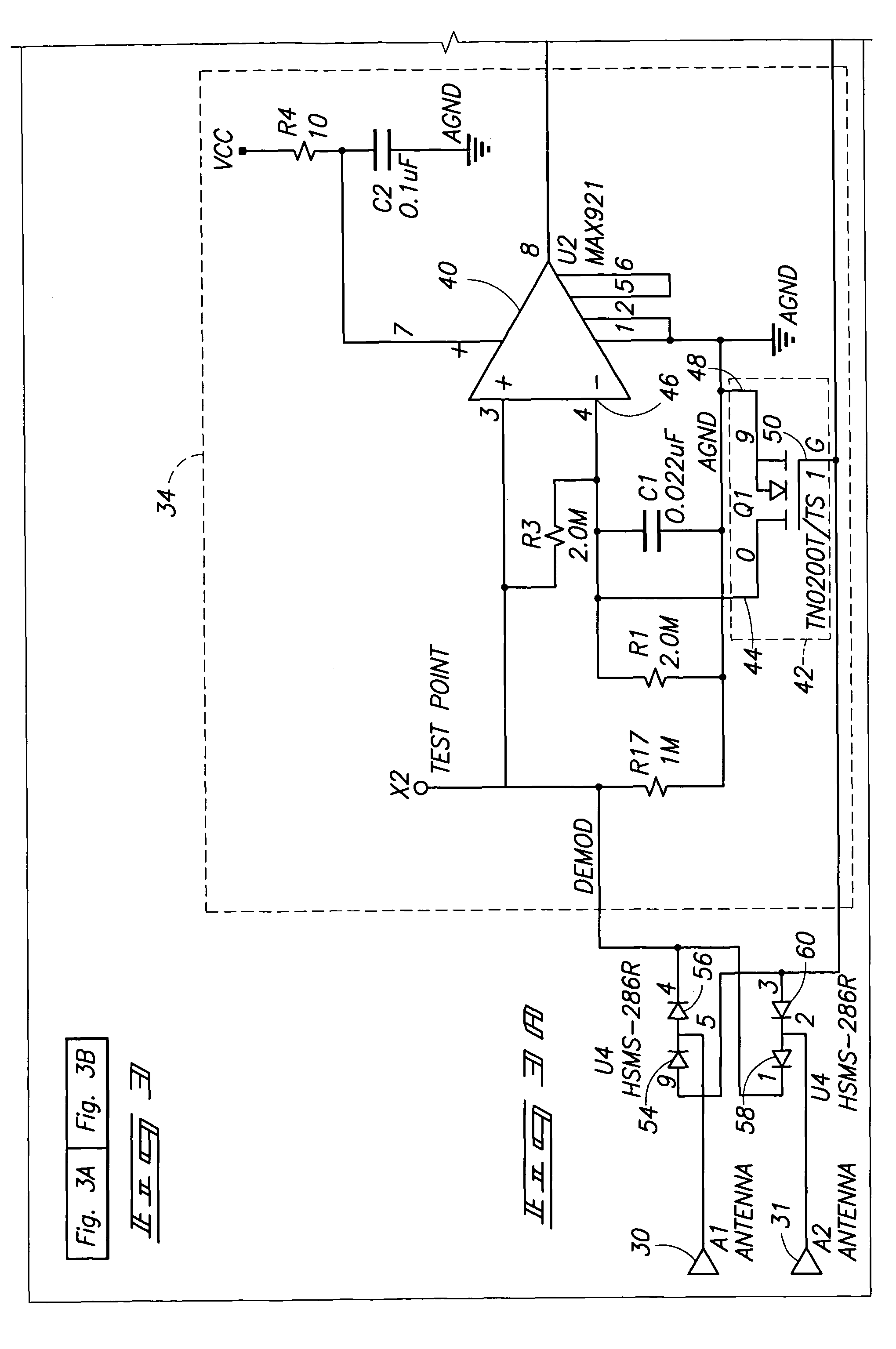
[0015]Attention is directed to the following commonly assigned applications, which are incorporated herein by reference: U.S. patent application Ser. No. 10 / 263,826, filed Oct. 2, 2002, Publication No. 2004-0066752, entitled “Radio Frequency Identification Device Communications Systems, Wireless Communication Devices, Wireless Communication Systems, Backscatter Communication Methods, Radio Frequency Identification Device Communication Methods, and a Radio Frequency Identification Device” by inventors Michael A. Hughes and Richard M. Pratt; U.S. patent application Ser. No. 10 / 263,809, filed Oct. 2, 2002, Publication No. 2004-0198222, entitled “Method of Simultaneously Reading Multiple Radio Frequency Tags, RF Tag, and RF Reader”, by inventors Emre Ertin, Richard M. Pratt, Michael A. Hughes, Kevin L. Priddy, and Wayne M. Lechelt; U.S. patent application Ser. No. 10 / 263,873, filed Oct. 2, 2002, Publication No. 2004-0066279, entitled “RFID System and Method Including Tag ID Compression”...


PUM


Abstract

A modulated backscatter radio frequency identification device includes a diode detector configured to selectively modulate a reply signal onto an incoming continuous wave; communications circuitry configured to provide a modulation control signal to the diode detector, the diode detector being configured to modulate the reply signal in response to be modulation control signal; and circuitry configured to increase impedance change at the diode detector which would otherwise not occur because the diode detector rectifies the incoming continuous wave while modulating the reply signal, whereby reducing the rectified signal increases modulation depth by removing the reverse bias effects on impedance changes. Methods of improving depth of modulation in a modulated backscatter radio frequency identification device are also provided.

Description

GOVERNMENT RIGHTS STATEMENT[0001]This invention was made with Government support under Contract DE-AC0676RL01830 awarded by the U.S. Department of Energy. The Government has certain rights in the invention.TECHNICAL FIELD[0002]The invention relates to wireless communications systems, radio frequency identification devices, wireless communications methods, and radio frequency identification device communications methods.BACKGROUND OF THE INVENTION[0003]Remote wireless communications may be implemented using radio frequency (RF) technology. Exemplary applications utilizing RF technology include identification applications including, for example, locating, identifying, and tracking of objects. Radio frequency identification device (RFID) systems have been developed to facilitate identification operations. For example, one device may be arranged to output and receive radio frequency communications and one or more remotely located devices may be configured to communicate with the one dev...

Claims


Application Information

Patent Timeline
Patent Type & Authority Patents(United States)
IPC IPC(8): H04Q5/22
CPCG06K19/0723
Inventor SCOTT, JEFFREY WAYNEPRATT, RICHARD M.
Owner BATTELLE MEMORIAL INST
Why Eureka
Try Eureka