Skew-correcting apparatus using external communications element

a communication element and skew correction technology, applied in the field of skew correction apparatus, can solve problems such as misalignment to the standard, different alignments of data bus lines, etc., and achieve the effect of eliminating any skew related problems

Inactive Publication Date: 2010-07-20
INTEL CORP
View PDF33 Cites 5 Cited by
  • Summary
  • Abstract
  • Description
  • Claims
  • Application Information

AI Technical Summary

Benefits of technology

[0012]This is different from the current systems on the market that involve grouping bus lines with each group having its own clock domain (U.S. Pat. No. 6,839,862, Evoy, Pontius & Ehmann, 2005) or by using multiple synchronization codes (U.S. Pat. No. 6,920,576, Ehmann, 2005). As Evoy et al. describe, “by grouping the bus lines in groups with each group having its own clock domain, skew across clock-domain groups is tolerated and overcome by processing the data and the skew first within each clock domain group, and then between groups.” Ehmann's solution “overcomes skewing problems by transferring digital data with automatic realignment,” i.e., using synchronization codes.
[0013]The proposed system of the present invention uses neither separate clock domains for bus line groups, nor adds synchronization codes, but rather employs internal loopback, combined with information collected from the connected communications element received path, to determine skew characteristics for each bus line. The skew can then be corrected by injecting offsetting skew amounts into the individual bus lines to re-align the data according to a single reference lane, thus eliminating any skew related problems and meeting all relevant standards.

Problems solved by technology

This skew can result in different alignments between lines of the data bus.
Each one of these transceivers may have different skew characteristics and therefore may cause misalignment to the standard when transmitting data.

Method used


Image

  • Skew-correcting apparatus using external communications element
  • Skew-correcting apparatus using external communications element
  • Skew-correcting apparatus using external communications element

Examples


example 1

Internal Loopback with Receive Path Information

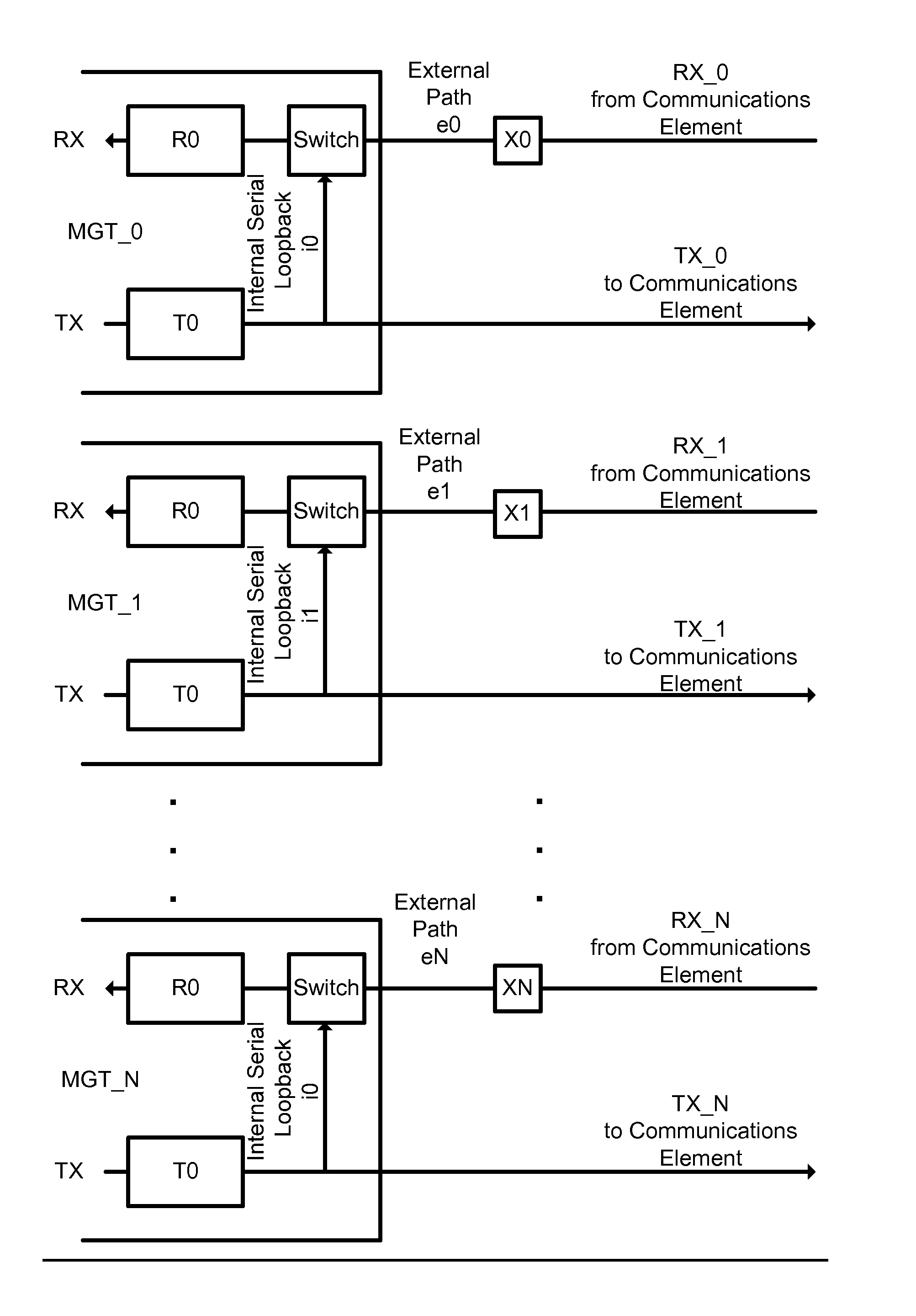
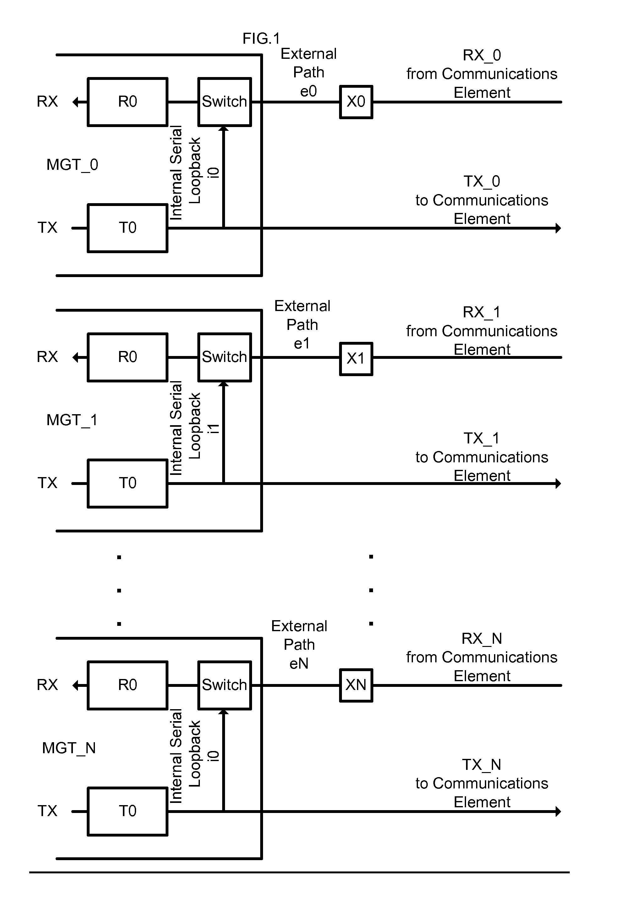
[0022]The system in this case is implemented using internal loopback and the information collected from the receive path from a single transceiver, that information being looped back from transmitter to receiver in that transceiver via a switch in the receive path, as shown in FIG. 1. The skew data from each transceiver will be used in conjunction with the data from the other transceivers to determine skew between each lane, and thus be able to correct it.

[0023]In Example 1, internal loopback is used in conjunction with the receive path to determine the relative skew amounts for each lane as illustrated in FIG. 1. The variables and constants used in this example are defined as:

[0024]

Definition List 1TermDefinitionR0Unknown receive skew for MGT_0R1Unknown receive skew for MGT_1R2Unknown receive skew for MGT_2T0Unknown transmit skew for MGT_0T1Unknown transmit skew for MGT_1T2Unknown transmit skew for MGT_2X0Unknown external skew for path...


PUM


Abstract

An apparatus for determining the amount of skew to be injected into a high-speed data communications system of including a plurality of lanes having a data bus per lane, relative to a reference lane, for system skew compensation. By knowing the relative amount of skew that each lane requires for alignment, an appropriate amount of skew can be injected on each lane to provide alignment and thus compliancy with the SFI-5 and SxI-5 standards, in terms of data skew specifications. The relative skew amounts for each transmitting lane are determined using a methodology involving internal loopback and characteristics from a connected communications element to the chip receive path.

Description

CROSS-REFERENCE TO RELATED APPLICATIONS[0001]Not ApplicableSTATEMENT REGARDING FEDERALLY SPONSORED RESEARCH OR DEVELOPMENT[0002]Not ApplicableREFERENCE TO SEQUENCE LISTING, A TABLE, OR A COMPUTER PROGRAM LISTING COMPACT DISC APPENDIX[0003]Not ApplicableBACKGROUND OF THE INVENTION[0004]1. Field of the Invention[0005]The present invention relates to chip-to-chip high speed data communications and the detection and correction of skew in each transmit channel, relative to a reference channel.[0006]2. Description of Related Art[0007]Parallel transmission, as defined with respect to the present invention, is the serial transmission of data over a plurality of lines on a data bus. In this parallel data transmission, skew can be added to each serial data lane through such means as serialization, cross-clock domain crossing, or through static skew parameters such as trace length. This skew can result in different alignments between lines of the data bus. Thus, there is an obvious need to cor...

Claims


Application Information

Patent Timeline
Patent Type & Authority Patents(United States)
IPC IPC(8): H03L7/00
CPCH04L1/242H04L25/14
Inventor HAAS, WALLYPITTMAN, MUTEMA JOHNRUMBOLT, CHUCK
Owner INTEL CORP
Why Eureka
Try Eureka