Magnet assembly for a conveyor system

a technology of conveyor system and magnet assembly, which is applied in the direction of mechanical conveyors, furnaces, charge manipulation, etc., can solve the problems of wasting a large amount of magnetic field, and achieve the effects of reducing production time, improving the life of the magnet assembly, and reducing the magnetic flux

Active Publication Date: 2010-07-27
INDAL MAGNETICS
View PDF29 Cites 20 Cited by
  • Summary
  • Abstract
  • Description
  • Claims
  • Application Information

AI Technical Summary

Benefits of technology

[0009]Encapsulating the magnetic circuit in the unitary housing prevents debris from the environment around the magnet assembly from interfering with the magnetic flux of the magnet assembly. Specifically, the unitary housing keeps the debris from attaching to the magnetic circuit and reducing the magnetic flux, thus improving the life of the magnet assembly, as well as allowing for use in applications where two-piece magnet assemblies previously could not be used. In addition, by forming the magnet assembly from the unitary housing is more simplistic than methods of the prior art, resulting in decreased production time and increased output. In addition, forming the magnet assembly from the unitary housing results in a more rigid design.

Problems solved by technology

First, the two-piece housing design does not completely seal off the magnets from debris in the environment outside the housing, which allows various particles to get inside the housing.
Since the ferromagnetic container only attaches to one surface of the magnet assembly, a portion of the magnetic field is wasted.

Method used


Image

  • Magnet assembly for a conveyor system
  • Magnet assembly for a conveyor system
  • Magnet assembly for a conveyor system

Examples


Embodiment Construction

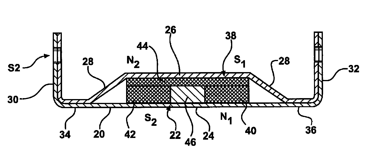
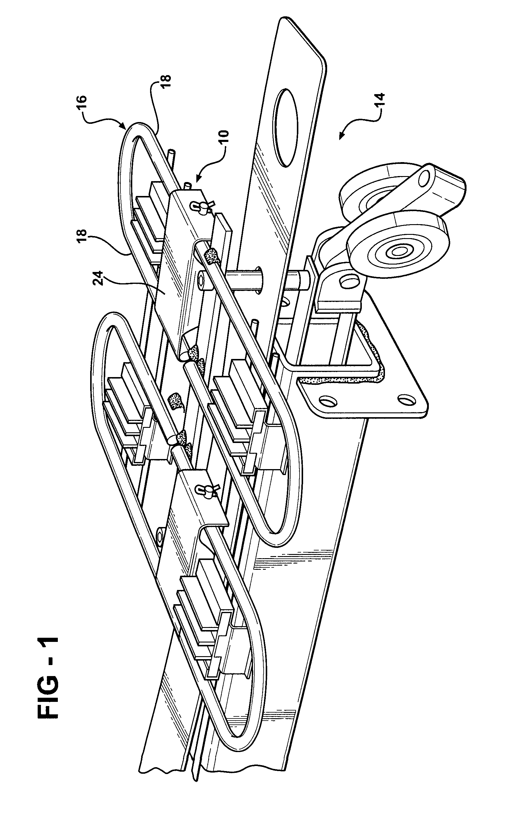
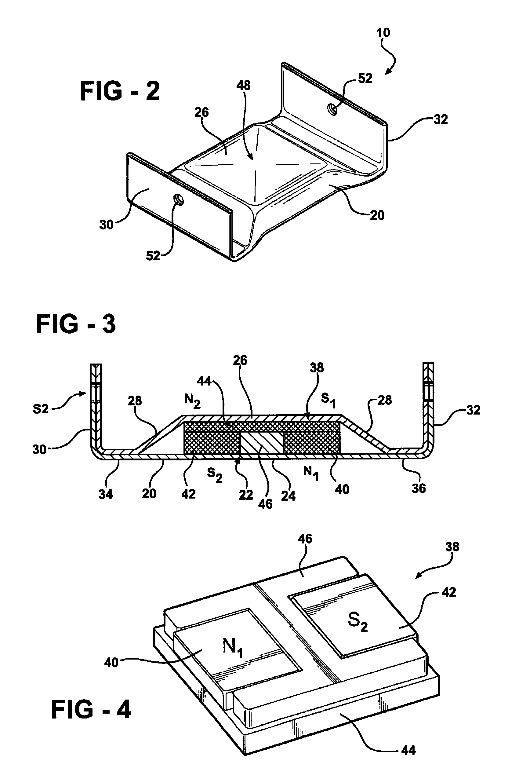
[0019]Referring to the Figures, wherein like numerals indicate corresponding parts throughout the several views, a magnet assembly is shown generally at reference numeral 10. The magnet assembly 10 as shown herein may be used with a conveyor system 12. The conveyor system 12 may be used for transporting a ferromagnetic container (not shown), such as a pan through a baking apparatus or any other device. The ferromagnetic container may be made of any material that is affected by a magnetic field. When used with the baking industry, the pan holds dough and the conveyor transports the pan through a proofer to make the dough rise. Next, the conveyor system 12 transports the pan through an oven to cook the dough. Therefore, the magnetic attraction of the ferromagnetic container to the magnetic field must be able to withstand temperatures typically used in a baking apparatus.

[0020]Even though the conveyor system 12 is described for use with a baking apparatus, it is to be understood that t...


PUM


Abstract

A magnet assembly for a conveyor system transporting a ferromagnetic container includes a housing having a unitary configuration. The housing defines a pocket, and a magnetic circuit is disposed in the pocket. The magnetic circuit produces a magnetic field having a magnetic flux. The magnetic circuit attracts the ferromagnetic container being transported by the conveyor system. In addition, a method of forming the magnet assembly to radiate the magnetic field includes providing the unitary housing having an opening and inserting the magnetic circuit into the unitary housing. The method further includes encapsulating the magnetic circuit in the unitary housing to form the magnet assembly.

Description

BACKGROUND OF THE INVENTION[0001]1. Field of the Invention[0002]The present invention generally relates to a magnet assembly for a conveyor system and a method of forming the magnet assembly.[0003]2. Description of the Related Art[0004]Various magnet assemblies used with conveyor systems are known in the art. Conveyor systems typically include a drive assembly and a grid disposed on the drive assembly. Generally, the grid includes at least one laterally extending support, such as a rail, and the magnet assembly rests upon the rail. The magnet assembly includes a magnetic circuit that generates a magnetic field having a magnetic flux along a contact surface of the magnet assembly. When transporting a ferromagnetic container with the conveyor system, the ferromagnetic container is supported by the grid and the magnet assembly holds the ferromagnetic container onto the grid.[0005]This type of conveyor system may be used by various industries, and specifically, the magnet assembly is us...

Claims


Application Information

Patent Timeline
Patent Type & Authority Patents(United States)
IPC IPC(8): B65G15/46
CPCB65G17/46
Inventor ALLORE, DANIEL
Owner INDAL MAGNETICS
Why Eureka
Try Eureka