Temperature sensor mounting structure and battery module structure

a technology for temperature sensors and mounting structures, which is applied in the direction of instruments, heat measurement, electric devices, etc., can solve the problems of difficulty in ensuring accurate positioning of temperature sensors, easy damage to temperature sensors, and inability to easily replace temperature sensors, etc., to achieve the effect of reducing both size and weight, simplifying the structure of movement restrictions, and improving the workability of attaching and removing harnesses

Active Publication Date: 2010-08-03
HONDA MOTOR CO LTD
View PDF44 Cites 32 Cited by
  • Summary
  • Abstract
  • Description
  • Claims
  • Application Information

AI Technical Summary

Benefits of technology

[0008]Therefore, the present invention provides a temperature sensor mounting structure that makes it possible to easily and accurately position a temperature sensor relative to a battery module and that also makes it possible to improve the temperature measurement accuracy, and provides a battery module structure that improves the workability when installing or removing a harness and the like.
[0044]According to the present invention, the shape of the harness can be properly organized and the wire connection workability can be improved.

Problems solved by technology

Moreover, maintenance such as replacing temperature sensors cannot be performed easily.
When a temperature sensor is firmly fixed to a battery module used in a hybrid vehicle or the like, in some cases where tape or a heat shrinkable tube is used, such structures may have a difficulty in ensuring accurate positioning of the temperature sensor, and in ensuring accurate temperature measurement as the temperature sensor can easily be affected by battery cooling air.
Moreover, in the latter conventional structure described above, because a harness and the like are wired using grooves in a side cover that extends across a plurality of battery modules, it is easy for the wiring path to become too complex, and replacement of battery module units is difficult.
This leads to a deterioration in the workability when attaching or removing the harness.

Method used


Image

  • Temperature sensor mounting structure and battery module structure
  • Temperature sensor mounting structure and battery module structure
  • Temperature sensor mounting structure and battery module structure

Examples


first embodiment

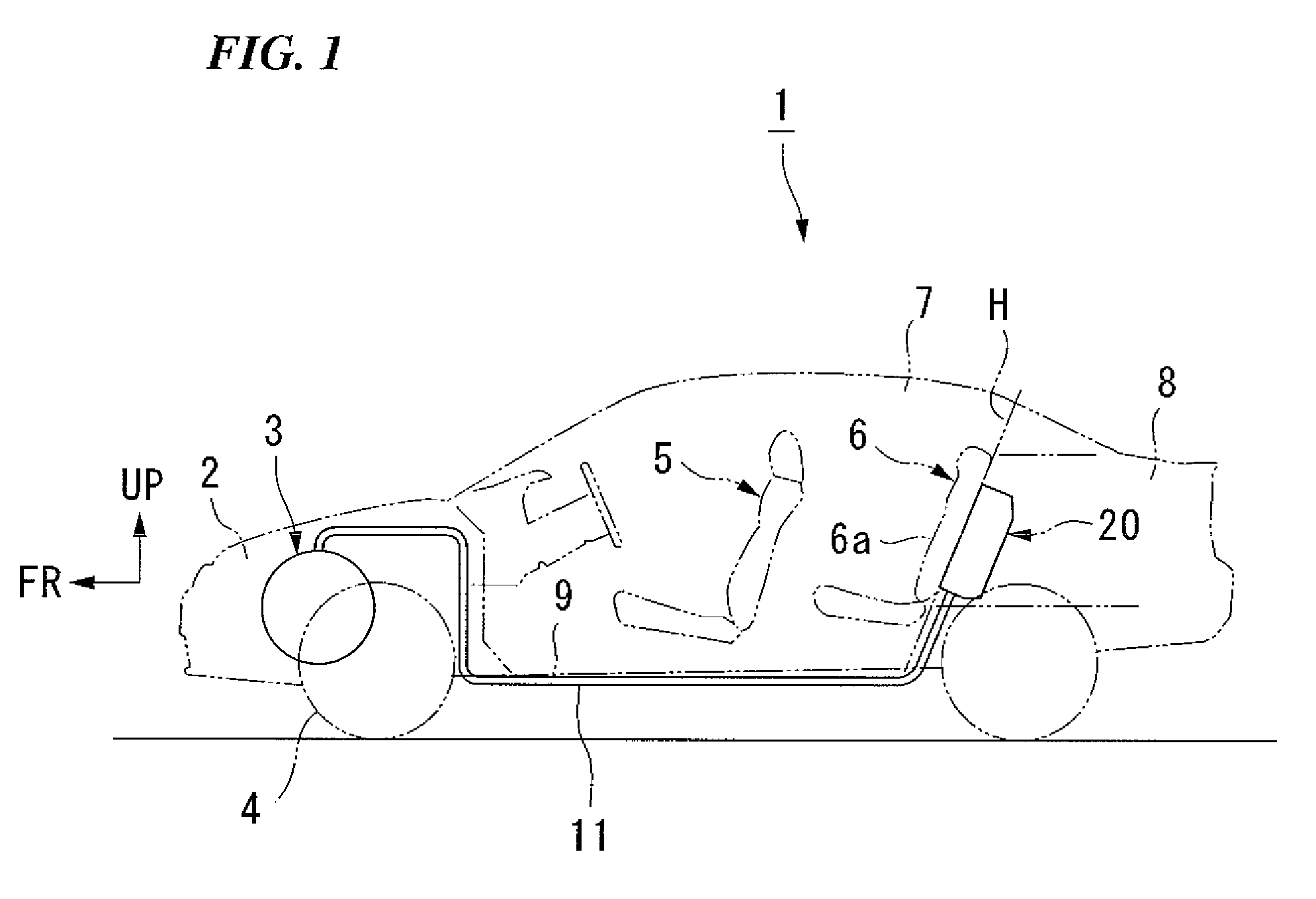
[0067]A vehicle 1 shown in FIG. 1 is a hybrid vehicle. Auxiliary driving is provided to an internal combustion engine by a motor generator, and when the vehicle decelerates and the like, kinetic energy can be recovered by the motor generator as electrical energy. Recovered electrical energy is used to charge an energy storage apparatus via a power converter.

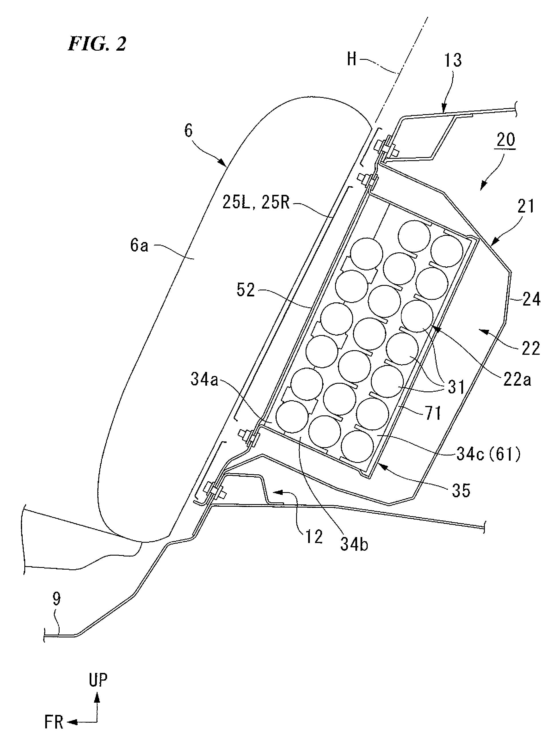
[0068]A power unit 3 that is formed by arranging the engine and motor generator in series is mounted in an engine room 2 in a front portion of a vehicle body of the vehicle 1. Drive power from the power unit 3 is transmitted to front wheels 4. A compartment 7 that has a front seat 5 and a back seat 6 is provided to the rear of the engine room 2, while a trunk room 8 that is partitioned off from the compartment 7 by a seat back 6a and the like of the back seat 6 is provided to the rear of the compartment 7. A high-voltage electrical equipment box 20 that is connected to the power unit 3 via a power cable 11 below a floor 9 is plac...

second embodiment

[0119]A second embodiment of the present invention will now be described.

[0120]This embodiment differs from the first embodiment in that, instead of the sensor cover 80, a sensor cover 100 is used that is mounted so as to sandwich the battery 31. Portions that are the same as those in the first embodiment are given the same descriptive symbols and a description thereof is omitted.

[0121]The sensor cover 100 shown in FIGS. 13, 14, and 15 is formed from a non-conductive resin in the same way as the sensor cover 80, and is formed by a pair of semicircular bodies 101 and 102 that match the shape of the outer circumference of the battery 31. End portions on one side in the circumferential direction of each of these semicircular bodies 101 and 102 form a hinge portion 104 as a result of their being connected, for example, via a flexible thin portion 103 (or via a hinge shaft).

[0122]When this hinge portion 104 is placed on the outer side in the vertical direction of the battery 31, the semi...

third embodiment

[0131]Next, a third embodiment of the present invention will be described.

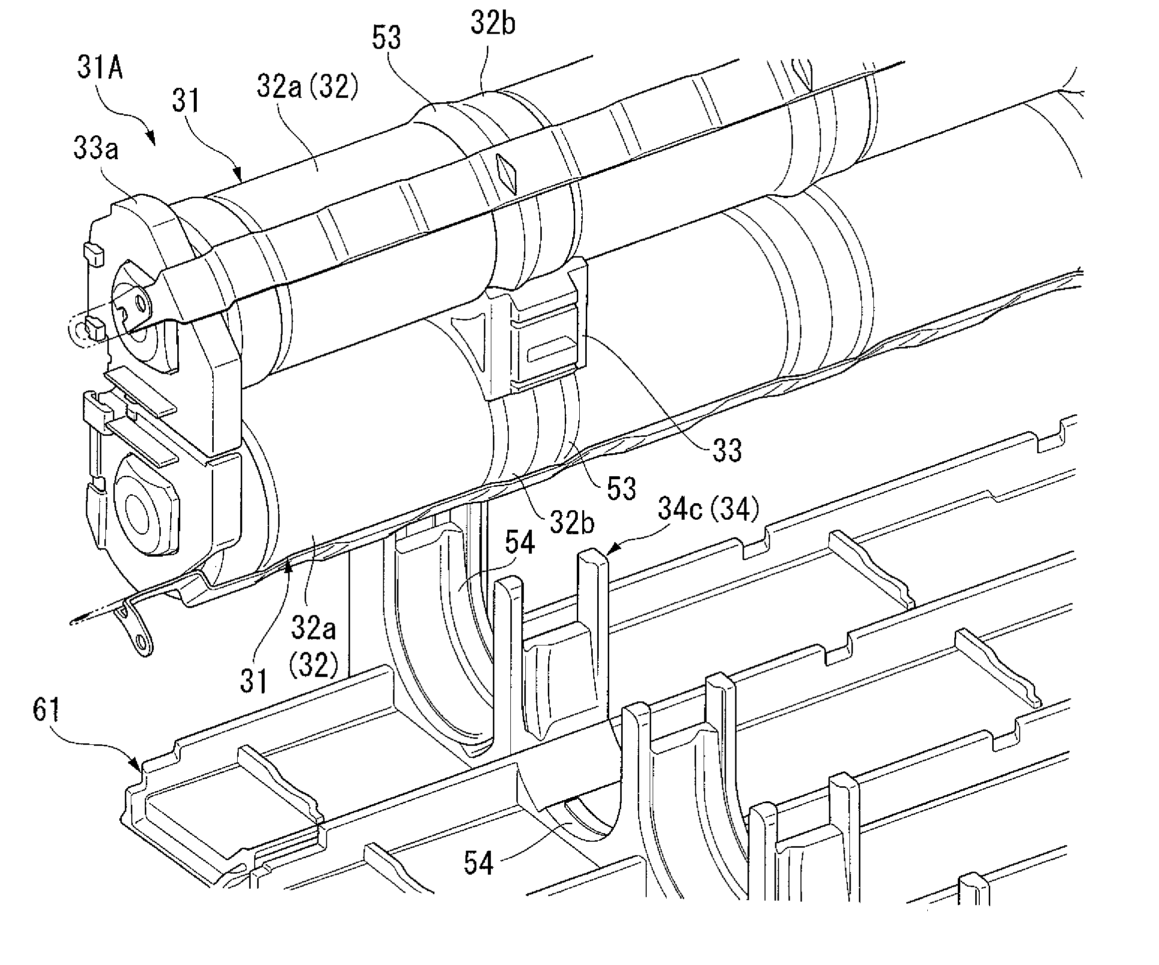
[0132]In this embodiment, a structure is employed in which a harness 128 (corresponding to the wires 76) of the temperature sensor 75 that is mounted on a battery module 121A is pulled out as far as an endplate 122 of this battery module 121A, and the harness 128 is held by a harness-fixing device that is provided on this endplate 122. Note that portions that are the same as those in the above-described embodiments are given the same descriptive symbols and a description thereof is omitted.

[0133]As is shown in FIG. 17 and FIG. 18, in the battery module 121A of this embodiment, a pair of batteries 31 are arranged next to each other so as to have alternate positive and negative poles, and the end portions thereof are connected together via an endplate 122. At this time, a predetermined gap is formed between the two batteries 31. These battery modules 121A are arranged in a plurality of parallel rows, and are sta...


PUM

PropertyMeasurementUnit
temperatureaaaaaaaaaa
movementaaaaaaaaaa
circumferenceaaaaaaaaaa

Abstract

A temperature sensor mounting structure for a battery module that is formed by connecting single cells together in series including: a temperature-measuring device that detects the temperature of the battery module; a covering device that covers the temperature-measuring device; and movement-restricting devices that are removably engaged with the battery module and restrict the movement of the covering device.

Description

TECHNICAL FIELD[0001]The present invention relates to a temperature sensor mounting structure in a battery module, and to a structure for this battery module.[0002]Priority is claimed on Japanese Patent Application Nos. 2005-131858, filed Apr. 28, 2005 and 2005-174994, filed Jun. 15, 2005, the contents of which are incorporated herein by reference.BACKGROUND OF THE INVENTION[0003]Conventionally, when a temperature sensor is firmly fixed to an object whose temperature is to be measured (hereinafter, “temperature measurement object”), the temperature sensor is mounted on the temperature measurement object using an adhesive agent (see, for example, Patent document 1).[0004]In contrast, when mounting a harness for a temperature sensor on a battery module that is used in a hybrid vehicle, in some cases grooves that are used to contain wiring for harnesses are provided in a side cover of a case that houses a plurality of battery modules (see, for example, Patent document 2).[Patent Docume...

Claims


Application Information

Patent Timeline
Patent Type & Authority Patents(United States)
IPC IPC(8): G01K1/08G01K7/00G01K13/00G01K1/14
CPCB60K1/04B60L3/0046B60L11/1872B60L11/1877H01M10/482H01M10/486B60L11/1879B60K2001/0416Y02T10/705B60L2260/56Y02T10/7005B60L58/25B60L50/66B60L50/64B60L58/26B60L53/80B60L58/18Y02T10/70Y02T10/7072Y02E60/10
Inventor SHIBUYA, KENTAROMARUNO, NAOKIMIZUTANI, ATSUSHIMATSUOKA, TOSHIYUKI
Owner HONDA MOTOR CO LTD
Why Eureka
Try Eureka